提示:文章写完后,目录可以自动生成,如何生成可参考右边的帮助文档
前言
- 加强掌握PWM开发流程
- 理解定时器与通道的关系
- 掌握多通道配置策略
- 掌握定时器查询方式
- 掌握代码抽取优化策略
内容
需求

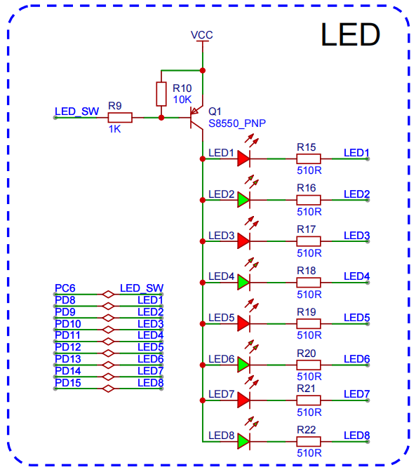
点亮4个灯,采用pwm的方式。
定时器 |
通道 |
引脚 |
AF |
LED序号 |
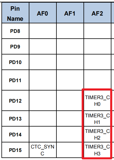
T3 |
CH0 |
PD12 |
AF2 |
LED5 |
CH1 |
PD13 |
AF2 |
LED6 |
|
CH2 |
PD14 |
AF2 |
LED7 |
|
CH3 |
PD15 |
AF2 |
LED8 |
实现LED5, LED6, LED7, LED8呼吸灯效果
通用定时器多通道
点亮T3定时器下的多个通道的灯。
开发流程
- 添加Timer依赖
- 初始化PWM相关GPIO
- 初始化PWM,包含多通道配置
- PWM占空比控制
多通道配置
void timer_channel_config(uint32_t timer_periph, uint16_t channel) {
  /* TIMER 通道输出配置 */
  timer_oc_parameter_struct ocpara;
  /* initialize TIMER channel output parameter struct */
  timer_channel_output_struct_para_init(&ocpara);
  /* 启用P极输出 */
  ocpara.outputstate  = (uint16_t)TIMER_CCX_ENABLE;
  /* 配置输出参数 configure TIMER channel output function */
  timer_channel_output_config(timer_periph, channel, &ocpara);
  /* 配置通道输出输出比较模式 configure TIMER channel output compare mode */
  timer_channel_output_mode_config(timer_periph, channel, TIMER_OC_MODE_PWM0);
}
输出比较模式
- TIMER_OC_MODE_PWM0: 高电平有效
- TIMER_OC_MODE_PWM1:低电平有效
占空比更新
/**********************************************************
 * @brief 更新pwm占空比
 * @param timer_periph 定时器
 * @param channel 通道
 * @param duty  占空比[0, 100]
 * @return
 **********************************************************/
void PWM_update(uint32_t timer_periph, uint16_t channel, float duty) { // 0-100

  if(duty > 100) duty = 100;
  else if(duty < 0) duty = 0;

//	pulse / PERIOD == duty / 100
  uint32_t pulse = PERIOD * duty / 100.0f - 1;

  // 计数值 65535
  timer_channel_output_pulse_value_config(timer_periph, channel, pulse);
}
完整代码
#include "gd32f4xx.h"
#include "systick.h"
#include <stdio.h>
#include "main.h"
#include "USART0.h"

void USART0_on_recv(uint8_t* data, uint32_t len) {
  printf("g_rx_buffer: %s g_rx_cnt:%d \n", data, len);
}

static void GPIO_config() {
  rcu_periph_clock_enable(RCU_GPIOC);
  gpio_mode_set(GPIOC, GPIO_MODE_OUTPUT, GPIO_PUPD_NONE, GPIO_PIN_6);
  gpio_output_options_set(GPIOC, GPIO_OTYPE_PP, GPIO_OSPEED_50MHZ, GPIO_PIN_6);

  gpio_bit_reset(GPIOC, GPIO_PIN_6);
}

void timer_gpio_config(uint32_t gpio_rcu, uint32_t gpio_port, uint32_t gpio_pin, uint32_t gpio_af) {
  rcu_periph_clock_enable(gpio_rcu);
  /* 设置gpio模式 */
  gpio_mode_set(gpio_port, GPIO_MODE_AF, GPIO_PUPD_NONE, gpio_pin);
  gpio_output_options_set(gpio_port, GPIO_OTYPE_PP, GPIO_OSPEED_MAX, gpio_pin);
  gpio_af_set(gpio_port, gpio_af, gpio_pin);
}

void timer_init_config(rcu_periph_enum rcu_periph, uint32_t timer_periph,
                       uint16_t t_prescaler, uint32_t t_period) {

  rcu_periph_clock_enable(rcu_periph);
  timer_deinit(timer_periph);
  /*初始化参数 */
  timer_parameter_struct initpara;
  /* initialize TIMER init parameter struct */
  timer_struct_para_init(&initpara);
  /* 根据需要配置值 分频系数 (可以实现更低的timer频率) */
  initpara.prescaler 	= t_prescaler - 1;
  /* 1个周期的计数(period Max: 65535) Freq > 3662  */
  initpara.period		= t_period - 1;
  /* initialize TIMER counter */
  timer_init(timer_periph, &initpara);
  /* enable a TIMER */
  timer_enable(timer_periph);

}

void timer_channel_config(uint32_t timer_periph, uint16_t channel) {
  /* TIMER 通道输出配置 */
  timer_oc_parameter_struct ocpara;
  /* initialize TIMER channel output parameter struct */
  timer_channel_output_struct_para_init(&ocpara);
  ocpara.outputstate  = (uint16_t)TIMER_CCX_ENABLE;
  /* 配置输出参数 configure TIMER channel output function */
  timer_channel_output_config(timer_periph, channel, &ocpara);
  /* 配置通道输出输出比较模式 configure TIMER channel output compare mode */
  timer_channel_output_mode_config(timer_periph, channel, TIMER_OC_MODE_PWM0);
}


// TIMER CH
#define LED5 TIMER3, TIMER_CH_0
#define LED6 TIMER3, TIMER_CH_1
#define LED7 TIMER3, TIMER_CH_2
#define LED8 TIMER3, TIMER_CH_3

// PWM
#define	PRESCALER		1
#define	FREQ			  10000
#define PERIOD			(SystemCoreClock / FREQ)

// LED5 TM3CH0 PD12
// LED6 TM3CH1 PD13
// LED7 TM3CH2 PD14
// LED8 TM3CH3 PD15
static void Timer_config() {
  // 定时器

  // GPIO ----------------------------------------
  timer_gpio_config(RCU_GPIOD, GPIOD, GPIO_PIN_12, GPIO_AF_2);
  timer_gpio_config(RCU_GPIOD, GPIOD, GPIO_PIN_13, GPIO_AF_2);
  timer_gpio_config(RCU_GPIOD, GPIOD, GPIO_PIN_14, GPIO_AF_2);
  timer_gpio_config(RCU_GPIOD, GPIOD, GPIO_PIN_15, GPIO_AF_2);

  // TIMER----------------------------------------
  /* 升级频率*/
  rcu_timer_clock_prescaler_config(RCU_TIMER_PSC_MUL4);
  timer_init_config(RCU_TIMER3, TIMER3, PRESCALER, PERIOD); // 与通道无关

  // TIMER channel-------------------------------
  timer_channel_config(LED5);
  timer_channel_config(LED6);
  timer_channel_config(LED7);
  timer_channel_config(LED8);

}

/**********************************************************
 * @brief 更新pwm占空比
 * @param timer_periph 定时器
 * @param channel 通道
 * @param duty  占空比[0, 100]
 * @return
 **********************************************************/
void PWM_update(uint32_t timer_periph, uint16_t channel, float duty) { // 0-100

  if(duty > 100) duty = 100;
  else if(duty < 0) duty = 0;

//	pulse / PERIOD == duty / 100
  uint32_t pulse = PERIOD * duty / 100.0f - 1;

  // 计数值 65535
  timer_channel_output_pulse_value_config(timer_periph, channel, pulse);
}

int main(void)
{
  systick_config();
  USART0_init();

  // 拉低总开关
//  GPIO_config();

  Timer_config();
  printf("Init Complete!\n");

  float duty = 0;
  int8_t dir = 1;
  while(1) {
    PWM_update(LED5, duty);
    PWM_update(LED6, duty);
    PWM_update(LED7, duty);
    PWM_update(LED8, duty);

    if (duty >= 100) {
      dir = -1;
    } else if (duty <= 0) {
      dir = 1;
    }
    duty += dir;

    printf("duty: %.2f \n", duty);

    delay_1ms(10);
  }
}
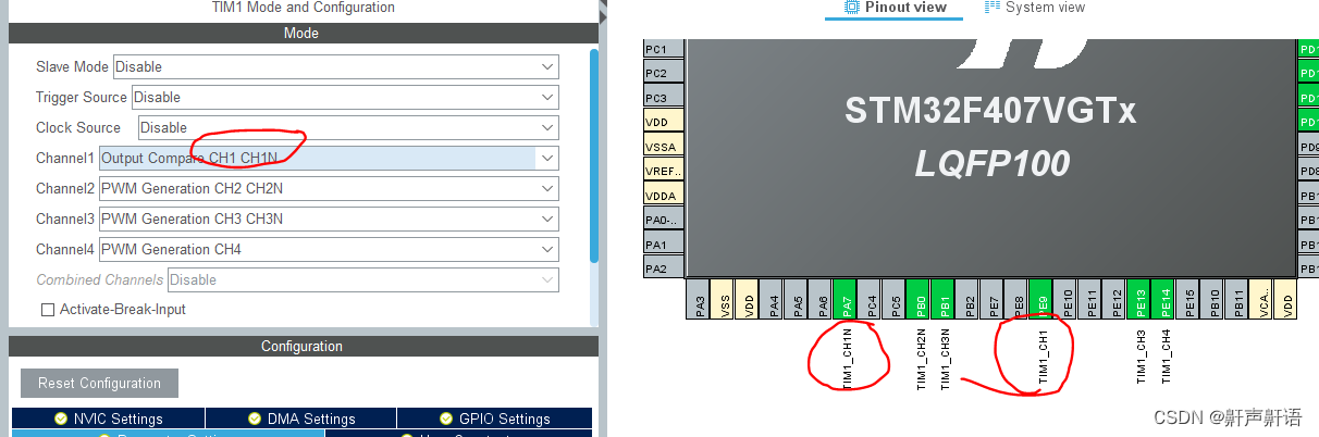
高级定时器通道输出
高级定时器只有TIMER0和TIMER7支持。由于扩展板上的高级定时器没有对应的LED,我们可以使用跳线的方式,将TIMER0CH0对应的PE8引脚,短接到PD8(LED1)上,通过观察LED1的亮灭,了解是否正确输出。
开发流程
- 添加Timer依赖
- 初始化PWM,包含多通道配置
- Break配置
- PWM占空比控制
通道配置
void timer0_channel_config(uint32_t timer_periph, uint16_t channel) {
  /* TIMER 通道输出配置 */
  timer_oc_parameter_struct ocpara;
  /* initialize TIMER channel output parameter struct */
  timer_channel_output_struct_para_init(&ocpara);
  // 禁用 OP极
//  ocpara.outputstate  = TIMER_CCX_ENABLE;
  // 启用 ON极
  ocpara.outputnstate = TIMER_CCXN_ENABLE;
  /* 配置输出参数 configure TIMER channel output function */
  timer_channel_output_config(timer_periph, channel, &ocpara);
  /* 配置通道输出输出比较模式 configure TIMER channel output compare mode */
  timer_channel_output_mode_config(timer_periph, channel, TIMER_OC_MODE_PWM0);
}

#define LED1 TIMER0, TIMER_CH_0

timer0_channel_config(LED1);- 特别强调,这里的引脚分为P和N类型,不同引脚要配置不同的输出状态
Break配置
// break 只针对高级定时器TIMER0 & TIMER7,需要打开互补保护电路

/* TIMER通道互补保护电路 */
timer_break_parameter_struct breakpara;
/* 初始化TIMER break参数结构体 */
timer_break_struct_para_init(&breakpara);
/* break输入的极性 HIGH */
breakpara.breakpolarity   = TIMER_BREAK_POLARITY_HIGH;
/* 输出自动的启用 */
breakpara.outputautostate = TIMER_OUTAUTO_ENABLE;
/* bread输入的启用*/
breakpara.breakstate     = TIMER_BREAK_ENABLE;
/* 配置TIMER7 break */
timer_break_config(TIMER0, &breakpara);
/* 启用TIMER7 break */
timer_break_enable(TIMER0);- breakstate:break状态开启
- ouputostate:输出状态,自动开启
- breakpolarity:输出极性,高电平
完整代码
#include "gd32f4xx.h"
#include "systick.h"
#include <stdio.h>
#include "main.h"
#include "USART0.h"

void USART0_on_recv(uint8_t* data, uint32_t len) {
  printf("g_rx_buffer: %s g_rx_cnt:%d \n", data, len);
}

static void GPIO_config() {
  rcu_periph_clock_enable(RCU_GPIOC);
  gpio_mode_set(GPIOC, GPIO_MODE_OUTPUT, GPIO_PUPD_NONE, GPIO_PIN_6);
  gpio_output_options_set(GPIOC, GPIO_OTYPE_PP, GPIO_OSPEED_50MHZ, GPIO_PIN_6);

  gpio_bit_reset(GPIOC, GPIO_PIN_6);
}

void timer_gpio_config(uint32_t gpio_rcu, uint32_t gpio_port, uint32_t gpio_pin, uint32_t gpio_af) {
  rcu_periph_clock_enable(gpio_rcu);
  /* 设置gpio模式 */
  gpio_mode_set(gpio_port, GPIO_MODE_AF, GPIO_PUPD_NONE, gpio_pin);
  gpio_output_options_set(gpio_port, GPIO_OTYPE_PP, GPIO_OSPEED_MAX, gpio_pin);
  gpio_af_set(gpio_port, gpio_af, gpio_pin);
}

void timer_init_config(rcu_periph_enum rcu_periph, uint32_t timer_periph,
                       uint16_t t_prescaler, uint32_t t_period) {

  rcu_periph_clock_enable(rcu_periph);
  timer_deinit(timer_periph);
  /*初始化参数 */
  timer_parameter_struct initpara;
  /* initialize TIMER init parameter struct */
  timer_struct_para_init(&initpara);
  /* 根据需要配置值 分频系数 (可以实现更低的timer频率) */
  initpara.prescaler 	= t_prescaler - 1;
  /* 1个周期的计数(period Max: 65535) Freq > 3662  */
  initpara.period		= t_period - 1;
  /* initialize TIMER counter */
  timer_init(timer_periph, &initpara);
  /* enable a TIMER */
  timer_enable(timer_periph);

}

void timer0_channel_config(uint32_t timer_periph, uint16_t channel) {
  /* TIMER 通道输出配置 */
  timer_oc_parameter_struct ocpara;
  /* initialize TIMER channel output parameter struct */
  timer_channel_output_struct_para_init(&ocpara);
  // 禁用 OP极
//  ocpara.outputstate  = TIMER_CCX_ENABLE;
  // 启用用 OP极
  ocpara.outputnstate = TIMER_CCXN_ENABLE;
  /* 配置输出参数 configure TIMER channel output function */
  timer_channel_output_config(timer_periph, channel, &ocpara);
  /* 配置通道输出输出比较模式 configure TIMER channel output compare mode */
  timer_channel_output_mode_config(timer_periph, channel, TIMER_OC_MODE_PWM0);
}

// TIMER CH
#define LED1 TIMER0, TIMER_CH_0

// PWM
#define	PRESCALER		1
#define	FREQ			  10000
#define PERIOD			(SystemCoreClock / FREQ)

// LED1 TM0CH0_ON PE8
static void Timer_config() {
  // 定时器

  // GPIO ----------------------------------------
  timer_gpio_config(RCU_GPIOE, GPIOE, GPIO_PIN_8,  GPIO_AF_1);

  // TIMER----------------------------------------
  /* 升级频率*/
  rcu_timer_clock_prescaler_config(RCU_TIMER_PSC_MUL4);
  timer_init_config(RCU_TIMER0, TIMER0, PRESCALER, PERIOD); // 与通道无关

  // TIMER channel-------------------------------
  timer0_channel_config(LED1);

  // Break --------------------------------------------------
  // break 只针对高级定时器TIMER0 & TIMER7,打开互补保护电路
  /* TIMER通道互补保护电路 */
  timer_break_parameter_struct breakpara;
  /* 初始化TIMER break参数结构体 */
  timer_break_struct_para_init(&breakpara);
  /* break输入的极性 HIGH */
  breakpara.breakpolarity   = TIMER_BREAK_POLARITY_HIGH;
  /* 输出自动的启用 */
  breakpara.outputautostate = TIMER_OUTAUTO_ENABLE;
  /* bread输入的启用*/
  breakpara.breakstate     = TIMER_BREAK_ENABLE;
  /* 配置TIMER7 break */
  timer_break_config(TIMER0, &breakpara);
  /* 启用TIMER7 break */
  timer_break_enable(TIMER0);
}

/**********************************************************
 * @brief 更新pwm占空比
 * @param timer_periph 定时器
 * @param channel 通道
 * @param duty  占空比[0, 100]
 * @return
 **********************************************************/
void PWM_update(uint32_t timer_periph, uint16_t channel, float duty) { // 0-100

  if(duty > 100) duty = 100;
  else if(duty < 0) duty = 0;

//	pulse / PERIOD == duty / 100
  uint32_t pulse = PERIOD * duty / 100.0f - 1;

  // 计数值 65535
  timer_channel_output_pulse_value_config(timer_periph, channel, pulse);
}

int main(void)
{
  systick_config();
  USART0_init();

  // 拉低总开关
  GPIO_config();

  Timer_config();
  printf("Init Complete!\n");

  float duty = 0;
  int8_t dir = 1;
  while(1) {
    PWM_update(LED1, duty);
    if (duty >= 100) {
      dir = -1;
    } else if (duty <= 0) {
      dir = 1;
    }
    duty += dir;

    printf("duty: %.2f \n", duty);

    delay_1ms(10);
  }
}
总结
高级定时器只有TIMER0和TIMER7支持。由于扩展板上的高级定时器没有对应的LED,我们可以使用跳线的方式,将TIMER0CH0对应的PE8引脚,短接到PD8(LED1)上,通过观察LED1的亮灭,了解是否正确输出。


![[leetcode]删除链表中倒数第k个结点](https://img-blog.csdnimg.cn/direct/bf767c4e72e44eea89a045e150ef4ea6.png)