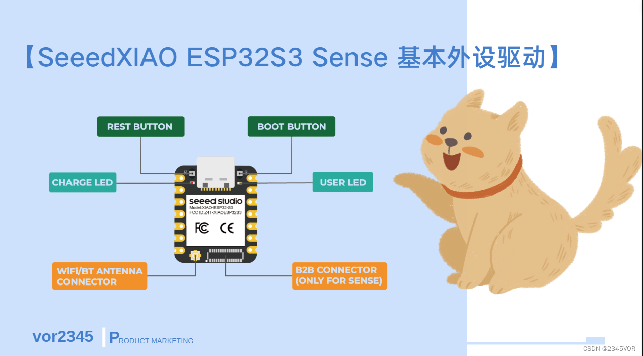
【SeeedXIAO ESP32S3 Sense 基本外设驱动】
活动地址:第四届2024年“寒假在家一起练”
资料地址:Seeed Studio XIAO ESP32S3 (Sense) 开发板
如果你是新手,可以先看这份【Seeed Studio XIAO ESP32S3 Sense 开箱Arduino教程】
本教程是参加2024年“寒假在家一起练”的【Seeed XIAO ESP32S3 Sense开发板】测评。
1. GPIO调试
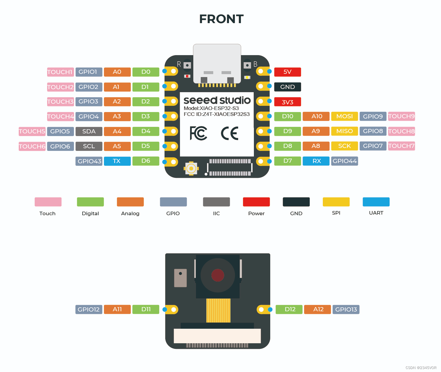
查看对应User_LED匹配IO21,源码修改如下,即可实现闪烁灯效果
1.1 源码分享
- 数字输出
/*
  Blink

  Turns an LED on for one second, then off for one second, repeatedly.

  Most Arduinos have an on-board LED you can control. On the UNO, MEGA and ZERO
  it is attached to digital pin 13, on MKR1000 on pin 6. LED_BUILTIN is set to
  the correct LED pin independent of which board is used.
  If you want to know what pin the on-board LED is connected to on your Arduino
  model, check the Technical Specs of your board at:
  https://www.arduino.cc/en/Main/Products

  modified 8 May 2014
  by Scott Fitzgerald
  modified 2 Sep 2016
  by Arturo Guadalupi
  modified 8 Sep 2016
  by Colby Newman

  This example code is in the public domain.

  https://www.arduino.cc/en/Tutorial/BuiltInExamples/Blink
*/

// the setup function runs once when you press reset or power the board
void setup() {

  // initialize digital pin LED_BUILTIN as an output.
  pinMode(LED_BUILTIN, OUTPUT);
}

// the loop function runs over and over again forever
void loop() {

  digitalWrite(LED_BUILTIN, HIGH);  // turn the LED on (HIGH is the voltage level)
  delay(1000);                      // wait for a second
  digitalWrite(LED_BUILTIN, LOW);   // turn the LED off by making the voltage LOW
  delay(1000);                      // wait for a second
}
一旦程序成功上传,您将看到以下输出消息,您可以观察到XIAO ESP32S3右侧的橙色LED正在闪烁。
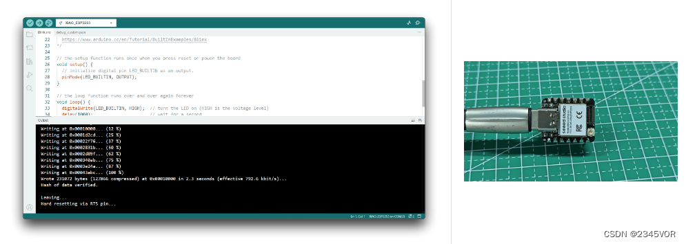
祝贺你,你已经学会了如何为XIAO ESP32S3编写和上传程序!👍👍👍
:::提示 只有当XIAO ESP32S3上的用户LED引脚设置为高电平时,LED才会熄灭,只有当引脚设置为低电平时,它才会点亮。 :::
- 下面是呼吸灯驱动LED PWM输出案例
/*
  Fading

  This example shows how to fade an LED using the analogWrite() function.

  The circuit:
  - LED attached from digital pin 9 to ground through 220 ohm resistor.

  created 1 Nov 2008
  by David A. Mellis
  modified 30 Aug 2011
  by Tom Igoe

  This example code is in the public domain.

  https://www.arduino.cc/en/Tutorial/BuiltInExamples/Fading
*/

int ledPin = 21;  // LED connected to digital pin 9

void setup() {

  // nothing happens in setup
}

void loop() {

  // fade in from min to max in increments of 5 points:
  for (int fadeValue = 0; fadeValue <= 255; fadeValue += 5) {

    // sets the value (range from 0 to 255):
    analogWrite(ledPin, fadeValue);
    // wait for 30 milliseconds to see the dimming effect
    delay(30);
  }

  // fade out from max to min in increments of 5 points:
  for (int fadeValue = 255; fadeValue >= 0; fadeValue -= 5) {

    // sets the value (range from 0 to 255):
    analogWrite(ledPin, fadeValue);
    // wait for 30 milliseconds to see the dimming effect
    delay(30);
  }
}
1.2 实验效果
板载LED灯分别会呈现闪烁或呼吸效果🤣🤣🤣
2. ADC调试
在文件实例基础中选择AnalogRead
查看对应模拟量端口匹配IO00~01,源码修改如下,即可实现A0、A1端口读取模拟量并打印效果
2.1 源码分享
/*
  ReadAnalogVoltage

  Reads an analog input on pin 0, converts it to voltage, and prints the result to the Serial Monitor.
  Graphical representation is available using Serial Plotter (Tools > Serial Plotter menu).
  Attach the center pin of a potentiometer to pin A0, and the outside pins to +5V and ground.

  This example code is in the public domain.

  https://www.arduino.cc/en/Tutorial/BuiltInExamples/ReadAnalogVoltage
*/

// the setup routine runs once when you press reset:
void setup() {

  // initialize serial communication at 9600 bits per second:
  Serial.begin(9600);
}

// the loop routine runs over and over again forever:
void loop() {

  // read the input on analog pin 0:
  int sensorValue = analogRead(A0);
  // Convert the analog reading (which goes from 0 - 4095) to a voltage (0 - 5V):
  float voltage = sensorValue * (3.34 / 4095.0);
  // print out the value you read:
  Serial.println(voltage);
  delay(100);
}
在setup()函数中,初始化串口通信模块,设置波特率为9600bps,xiao开发板模数转换器(Analog-to-Digital Converter,ADC)的分辨率到12位(0~4096)。
在loop()函数中:
- 读取从板子的第1个模拟端口(analog pin 1)获得模拟值,并存储在变量sensorValue 中;
- 将该模拟值转换成V,并存储在变量voltage 中;
- 输出voltage 值到串口中;
- 延时100ms,以防止误读。
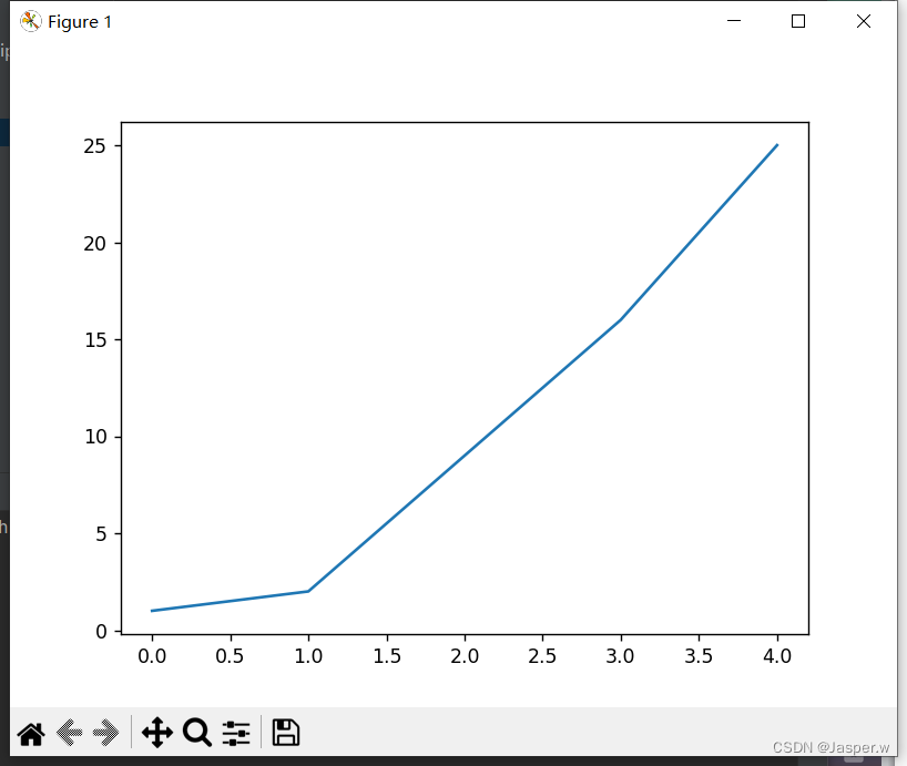
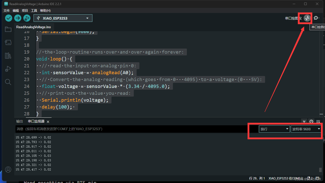
2.2 实验效果
A0手动接触,看其变化,串口绘图仪效果如下

3. 麦克风测试
安装扩展板(for Sense)
安装扩展板非常简单,只需要将扩展板上的连接器对准小ESP32S3上的B2B连接器,然后用力按下,听到“咔”的一声,安装完成。

3.1 声音响度检测
在第一个项目案例中,我们使用Arduino IDE的串口波形图来检测环境中的噪声,并展示麦克风检测到的环境响度。
下面是完整的示例程序。
#include <I2S.h>

void setup() {

  // Open serial communications and wait for port to open:
  // A baud rate of 115200 is used instead of 9600 for a faster data rate
  // on non-native USB ports
  Serial.begin(115200);
  while (!Serial) {

    ; // wait for serial port to connect. Needed for native USB port only
  }

  // start I2S at 16 kHz with 16-bits per sample
  I2S.setAllPins(-1, 42, 41, -1, -1);
  if (!I2S.begin(PDM_MONO_MODE, 16000, 16)) {

    Serial.println("Failed to initialize I2S!");
    while (1); // do nothing
  }
}

void loop() {

  // read a sample
  int sample = I2S.read();

  if (sample && sample != -1 && sample != 1) {

    Serial.println(sample);
  }
}
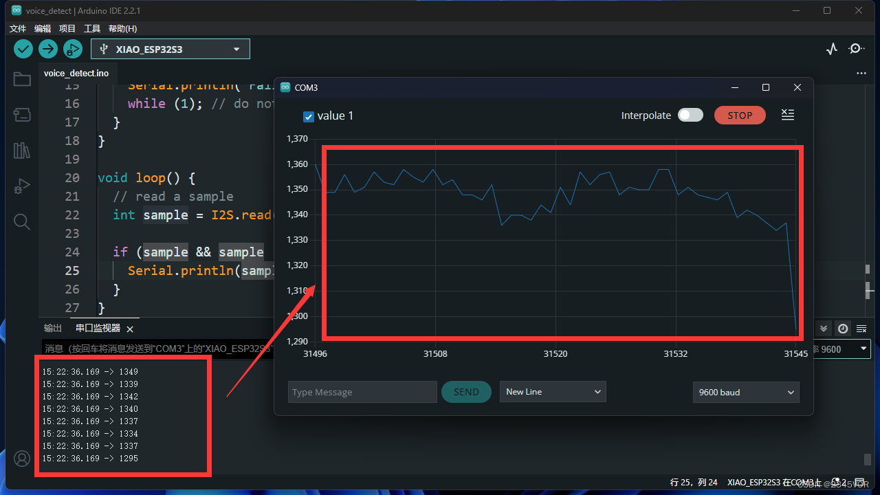
上传此程序为XIAO ESP32S3 Sense并打开Serial Plotter,您将看到声音的响度变化曲线。
3.2 程序注释
在程序开始时,为了使用麦克风引脚,我们首先需要导入I2S库。
#include <I2S.h>
在I2S对象上调用setAllPins()函数来配置I2S接口使用的引脚。该函数接受5个整数参数,分别表示连接到I2S接口的位时钟、单词选择、数据输入、数据输出和通道选择线的GPIO引脚。
I2S.setAllPins(-1, 42, 41, -1, -1);
在这个特定的代码中,-1值表示没有使用相应的引脚,而42和41值分别表示连接到单词选择和数据输入行的GPIO引脚。数据输出和通道选择行在此配置中不使用,而是设置为-1。
if (!I2S.begin(PDM_MONO_MODE, 16000, 16)) {

    Serial.println("Failed to initialize I2S!");
    while (1); // do nothing
}
在I2S对象上调用begin()函数,用指定的参数初始化I2S接口:PDM_MONO_MODE、16000 Hz采样率和16-bit分辨率。
TIPs: 值得注意的是,对于目前的ESP32-S3芯片,我们只能使用PDM_MONO_MODE,采样位宽只能为16bit。只有采样率可以修改,但经过测试,16kHz的采样率比较稳定。
int sample = I2S.read();

if (sample && sample != -1 && sample != 1) {

    Serial.println(sample);
}
3.3 实验效果
在I2S对象上调用read()函数,从I2S接口读取单个音频样本。if语句检查sample变量的值。如果采样值不是0、-1或1,它就被认为是有效的音频采样,并且If块中的代码会被执行。在这种情况下,使用 serial .println()函数将样本值打印到串行控制台。
具体保存到SD卡教程见:https://wiki.seeedstudio.com/cn/xiao_esp32s3_sense_mic/
4. 双cpu双线程测试
ESP32-C3 系列芯片,搭载 RISC-V 32 位双核处理器。那就可以跑多线程,下面就是两个线程。程序中避免有过多的延迟函数😘😘😘
4.1 源码分享
int testdata0 = 10;
int testdata1 = 0;

void CpuLoop(void *pvParameters){

  while(1){

    Serial.println("cpu"+String(xPortGetCoreID())+"---testdata0:"+String(testdata0));
    testdata1 ++;
    if(testdata1 == 10)
    testdata1 = 0;
    delay(2000);
  }

  vTaskDelete(NULL);
}
void setup() {

    Serial.begin(9600);
    xTaskCreatePinnedToCore(CpuLoop,    //具体实现的函数
                            "CPU_LOOP",  //任务名称
                            8192,       //堆栈大小
                            NULL,       //输入参数
                            1,          //任务优先级
                            NULL,       //
                            0           //核心  0\1
                            );
}

void loop() {

  Serial.println("cpu"+String(xPortGetCoreID())+"---testdata1:"+String(testdata1));
  testdata0 --;
  if(testdata0 == 0)
    testdata0 = 10;
  delay(1000);
}
设置串口波特率为9600bps。
在setup()函数中创建一个名为“CPU_LOOP”的任务,并将其实现的函数appCpuLoop()、堆栈大小为8192、输入参数为空、优先级为1、绑定到核心0上进行运行。
在CpuLoop()函数中,当while循环条件为真时,持续执行循环体内的内容。首先打印出字符串“Cpu1”和变量testdata0相加的结果,然后让testdata1自增1,如果testdata1等于10,则将其值设为0;最后延时2000毫秒后继续下一次循环。
在loop()函数中默认是在cpu核心1上运行,打印出字符串“cpu0”和变量testdata1相加的结果,然后让testdata0自减1,如果testdata0等于0,则将其值设为10;最后延时1000毫秒后继续下一次循环。
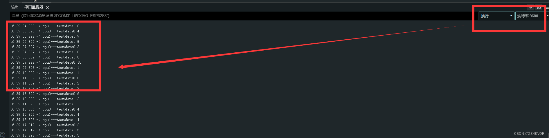
4.2 测试效果
打开串口显示两个内核运行效果
5. BLE蓝牙和安卓端蓝牙数据交互实验
🔖ESP32低功耗(BLE)蓝牙实验.
🛠调试工具
🔧安卓系统BLE调试工具:BLEAssist
📍APP下载地址:http://www.wch.cn/downloads/BLEAssist_ZIP.html
首先安装BLE调试助手
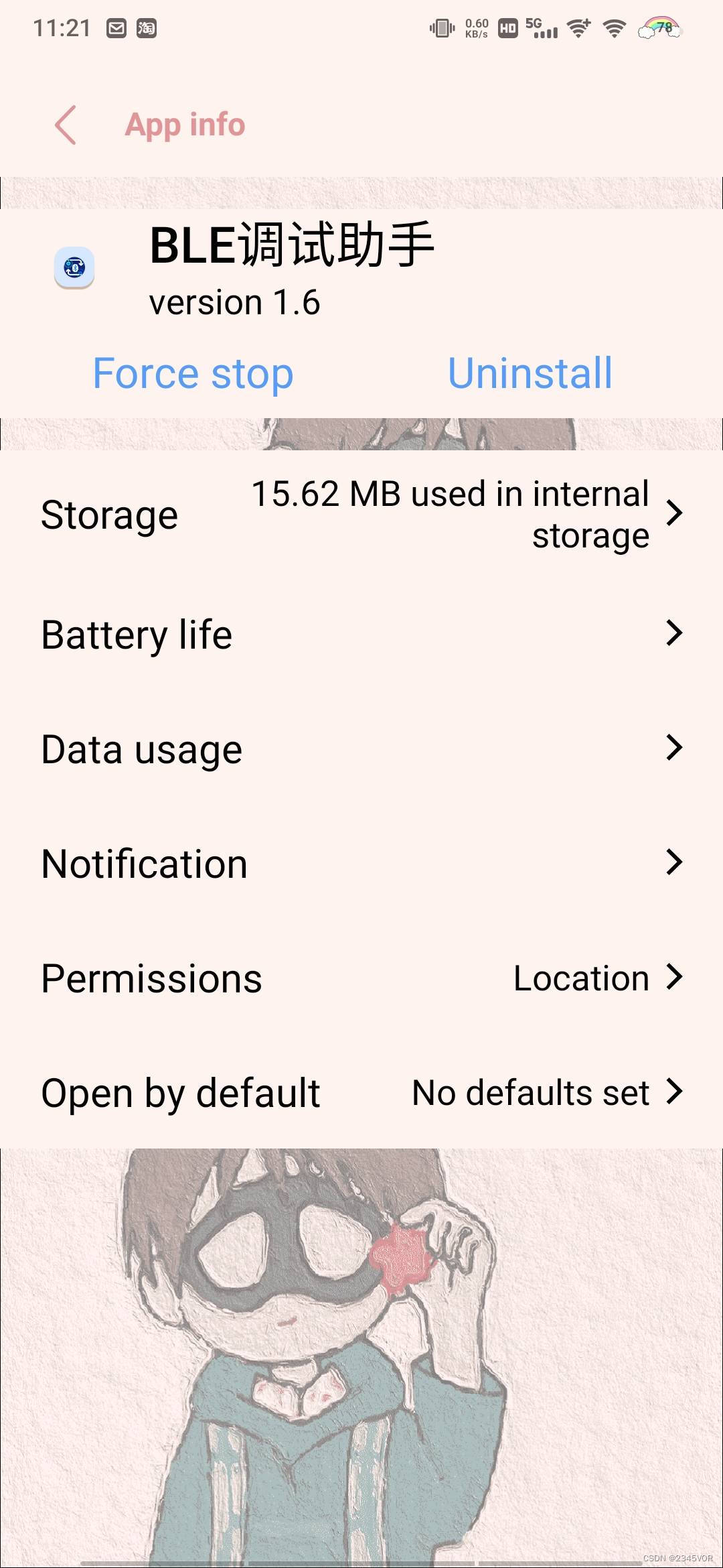
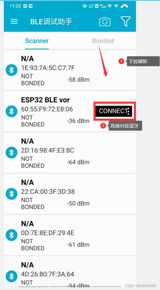
安装后打开,下拉刷新蓝牙,连接对应蓝牙
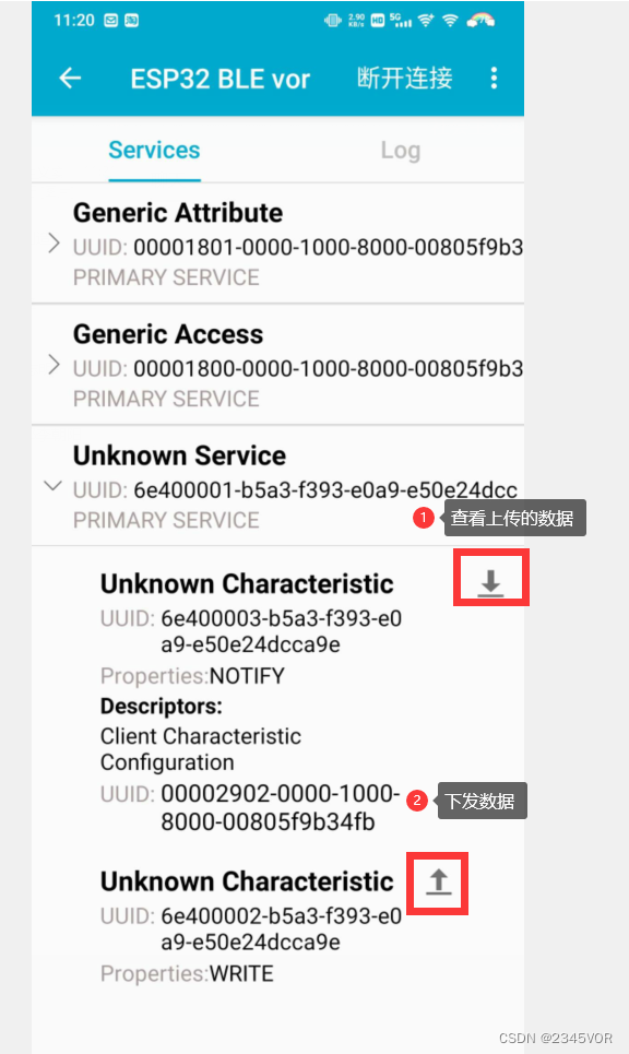
在第三项中选择查看和发送数据
5.1 源码分享
#include <BLEDevice.h>
#include <BLEServer.h>
#include <BLEUtils.h>
#include <BLE2902.h>

BLECharacteristic *pCharacteristic;
bool deviceConnected = false;
char BLEbuf[32] = {
    0 };
uint32_t cnt = 0;
String message_c;
int i = 0;
#define SERVICE_UUID "6E400001-B5A3-F393-E0A9-E50E24DCCA9E"  // UART service UUID
#define CHARACTERISTIC_UUID_RX "6E400002-B5A3-F393-E0A9-E50E24DCCA9E"
#define CHARACTERISTIC_UUID_TX "6E400003-B5A3-F393-E0A9-E50E24DCCA9E"

class MyServerCallbacks : public BLEServerCallbacks {

  void onConnect(BLEServer *pServer) {

    deviceConnected = true;
  };

  void onDisconnect(BLEServer *pServer) {

    deviceConnected = false;
  }
};

class MyCallbacks : public BLECharacteristicCallbacks {

  void onWrite(BLECharacteristic *pCharacteristic) {

    std::string rxValue = pCharacteristic->getValue();

    if (rxValue.length() > 0) {

      Serial.print("------>Received Value: ");

      for (int i = 0; i < rxValue.length(); i++) {

        Serial.print(rxValue[i]);
      }
      Serial.println();
    }
  }
};
void setup() {

  Serial.begin(115200);

  // Create the BLE Device
  BLEDevice::init("ESP32 BLE Test");

  // 创建蓝牙服务器
  BLEServer *pServer = BLEDevice::createServer();
  pServer->setCallbacks(new MyServerCallbacks());

  // // 创建广播服务的UUID
  BLEService *pService = pServer->createService(SERVICE_UUID);

  // 创建广播服务的UUID
  pCharacteristic = pService->createCharacteristic(CHARACTERISTIC_UUID_TX, BLECharacteristic::PROPERTY_NOTIFY);

  pCharacteristic->addDescriptor(new BLE2902());

  BLECharacteristic *pCharacteristic = pService->createCharacteristic(CHARACTERISTIC_UUID_RX, BLECharacteristic::PROPERTY_WRITE);

  pCharacteristic->setCallbacks(new MyCallbacks());

  // 开始蓝牙服务
  pService->start();

  // 开始广播
  pServer->getAdvertising()->start();
  Serial.println("Waiting a client connection to notify...");
}

void loop() {

  if (deviceConnected) {
     //设备连接后,每秒钟发送txValue。
    memset(BLEbuf, 0, 32);
    message_c = "s  " + String(i) + "\r\n";
    i++;
    char *p = const_cast<char *>(message_c.c_str());
    memcpy(BLEbuf, p, 32);
    pCharacteristic->setValue(BLEbuf);

    pCharacteristic->notify();  // Send the value to the app!
    Serial.print("*** Sent Value: ");
    Serial.print(BLEbuf);
    Serial.println(" ***");
  }
  delay(1000);
}
设置串口波特率为115200bps。
在setup()函数中:
- 使用BLEDevice类初始化Bluetooth Low Energy设备,并设定其名称为"ESP32 BLE Test";
- 创建并返回一个服务器对象,并将其回调函数设置为MyServerCallbacks类型的实例;
- 使用BLEServer类创建一个服务,并使用SERVICE_UUID定义该服务的唯一标识符;
- 在创建的服务中添加一个特性,该特性具有可写属性,其唯一标识符为CHARACTERISTIC_UUID_RX;
- 将可写特性的回调函数设置为MyCallbacks类型的实例; 启动创建的服务; 启动广告活动。
在loop()函数中:
- 检查设备是否已连接。如果设备已连接,则按照以下步骤执行: 清空BLEbuf数组;
- 定义一个字符串message_c,其中包含字符’s’和变量i的当前值,两者之间用空格分隔,并在其末尾添加换行符;
- 将message_c转换为字符指针类型,并复制到BLEbuf数组中; 设置特性值为BLEbuf数组的内容;
- 调用notify()方法向应用程序发送数据; 打印已经发送的数据;
延迟1000ms后继续下一次循环。
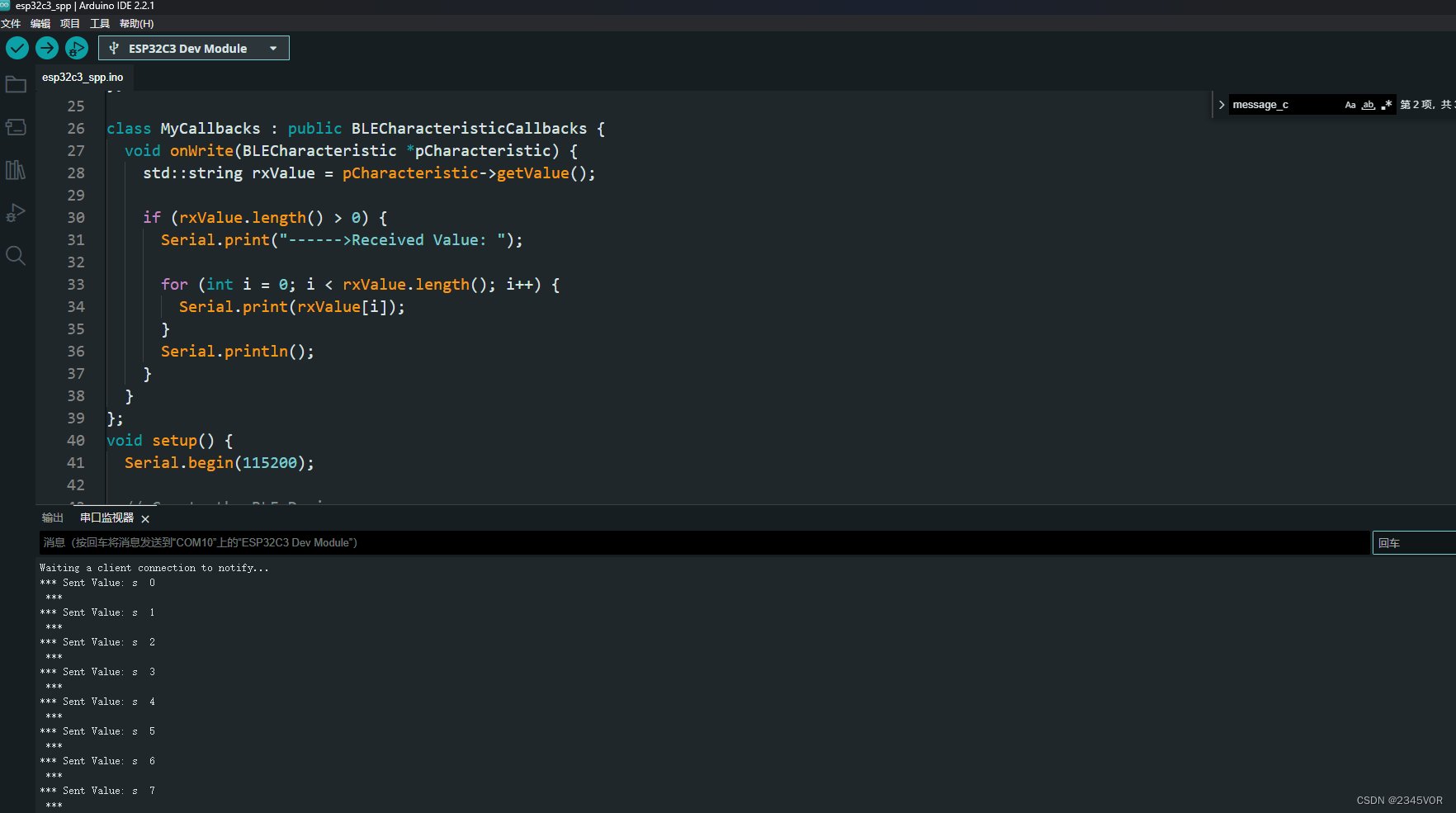
5.2 实验效果
esp32c3发送数据,手机接收数据

esp32c3接收数据,手机发送数据


6. 总结
通过SeeedXIAO ESP32S3 Sense 基本外设驱动教程,我们可以让ESP32作为主心骨,GPIO、ADC、麦克风、多线程、蓝牙外设有机衔接从而完成功能,进而丰富我们的生活。🛹🛹🛹
从而实现对外部世界进行感知,充分认识这个有机与无机的环境,科学地合理地进行创作和发挥效益,然后为人类社会发展贡献一点微薄之力。🤣🤣🤣
- 我会持续更新对应专栏博客,非常期待你的三连!!!🎉🎉🎉
- 如果鹏鹏有哪里说的不妥,还请大佬多多评论指教!!!👍👍👍
- 下面有我的🐧🐧🐧群推广,欢迎志同道合的朋友们加入,期待与你的思维碰撞😘😘😘