Introduction and scope
The intention of this document is to give an overview on Camx & Chi & Camer sensor driver software architecture design, implementation and debugging for Qcom platform customization SDM845/670/710 and later productions. From Qcom view, Camx & Chi design need consider ISP functions, customization, tuning and HAL3 supports.
From Qcom spectra 2xx ISP view, D-PHY1.2: 4/4/4, 2.5 Gbps/lane, and C-PHY1.0: 3T/3T/3T, 5.7 Gbps/T (3T = 17.1 Gbps) are supported. The difference between the SDM845 and 670/710 is that the SDM845 has a dual IPE and supports both 10 and 8 bit output , however, the SDM670/SDM710 has a single IPE and supports only 8 bit output.
Camera SW system description
Camera High level SW architecture
Following picture is the high level description for camera. HAL3/CHI is for all API-level customizations. CHI is for flow management and ISP register programming. CHI Node and Stats overrides are for “Algorithm Expert” customizations, for example MFNR, ZSL. CHI tuning overrides are for “IQ expert” overrides.
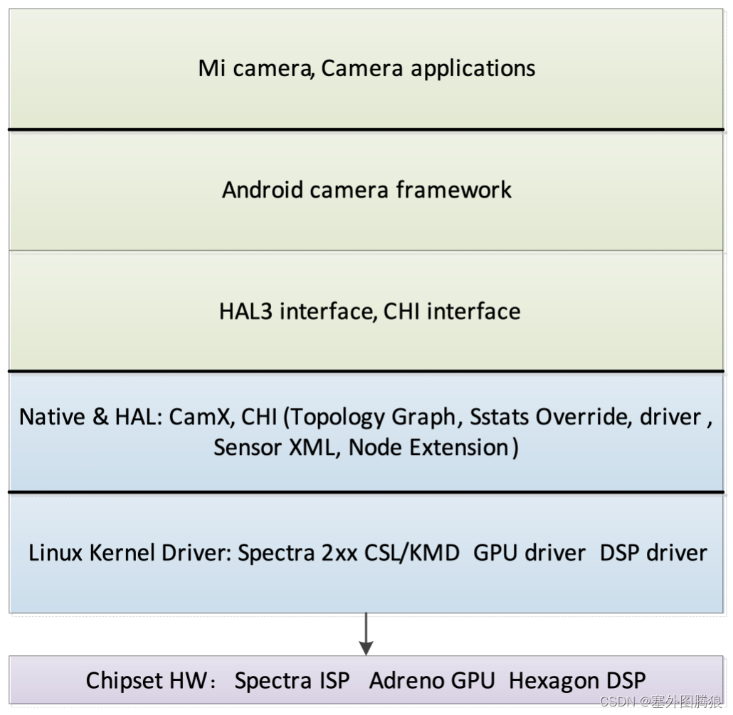
Figure 1. High level block diagram of the camera SW architecture
CHI Interface (Chi override module) – Be responsible for supplements the Google HAL3 interface to allow for explicit image processing pipeline generation, explicit engine selection, and multi frame control for any HAL3-compliant camera applications. Some of the features used by the extended Google HAL3 interface are given in the following list:
- Custom ZSL
- Multiframe request generation and processing
- Image stabilization
- Low latency post processing
For information on the extensions of the Google HAL3 API, see https://source.android.com/devices/camera/camera3.html
http://developer.android.com/reference/android/hardware/camera2/package-summary.html
https://developer.android.com/reference/android/hardware/camera2/params/package-summary
Chi topology graph – Which allows for an arbitrary compute pipeline to be constructed to process images. The pipeline can consist of fixed function ISP blocks (FF-ISP), provided by QTI, or extended nodes, which are completely controlled outside of the camera driver stack. The graph is specified by an XML file for different camera use cases. It is loaded when the HAL process is initialized. It is essentially a Key + Data store, where a key is useful to choose a specific data from the available set. The data in Chi topology XML is the DAG (topology) and the key is per-session settings + collection of streams. Qualcomm provides default topologies for common use cases. OEMs can edit the default XML and create their own topology XML containing custom topologies. The Chi API provides an interface to explicitly select a custom topology. The XML file must contain one root tag that is the parent of all other tags. <UsecaseDef> is the root tag. Every use case is defined with the <Usecase> tag. All the information related to a single use case exists between <Usecase> </Usecase>. It contains the keys for matching the use case, as well as the topology which defines the use case.
<Usecase> Valid tags:
- <UsecaseName> - Value field. Exactly 1 tag is required.
- <Targets> - Exactly 1 is required. List of streams, including formats, and ranges of sizes that the use case executes on. The streams listed here correspond to the streams passed into the HAL3 configure_streams() API
- <StreamConfigMode> - Value field. Exactly 1 is required.
- <SystemwideSetting> - Exactly 1 is required.
- <Topology> - At least 1 is required.
<Target> Description of a single stream or target. Individual tag values in this section are compared with the stream configuration passed into configure_streams() to find a matching <Usecase>. <Target> and <SystemwideSettings> are used to select a <Usecase> from the XML. Valid tags:
- <TargetName> - Value field. Exactly 1 is required.
- <TargetDirection> - Value field. Exactly 1 is required.
- <TargetFormat> - Value field. At least 1 is required.
- <Range> - Exactly 1 is required. The resolution of the buffer and the incoming resolution of the buffer in configure_streams() must fall within this range for the <Usecase> to be selected as a matching use case for the input stream configuration. Valid tags:
- <MinW> - Value field. Exactly 1 required.
- <MinH> - Value Field. Exactly 1 required.
- <MaxW> - Value Field. Exactly 1 required.
- <MaxH> - Value Field. Exactly 1 required.
For more details see ref[2].
Chi node interface –The Chi driver CAMX provides default nodes to enable the camera use cases. OEMs can add functionalities to the existing Chi driver CAMX for a unique camera experience. It is a simple yet powerful interface to seamlessly add image processing functionalities in the camera pipeline.
Chi node extensions – Are a further extension of Chi, which provide convenient hooks to streamline additional processing on the CPU, GPU (via OpenCL, OpenGL ES, or Vulkan), or DSP (via OpenDSP, FastCV software development kit, or custom programming). Custom nodes can specify the private vendor tags to be used by the application, and interact with Chi FF-ISP nodes or other extended nodes.
Chi stats overrides – Including 3A, which provide mechanisms to override any of QTI’s default stats algorithms, without the need for driver changes. External stats algorithms can store private data, which is also accessible by custom nodes.
Chi sensor XML – Allows device manufactures to define parameter-driven drivers for their specific hardware components including the camera module, the image sensor, actuators, electronically erasable programmable read-only memory (EEPROM), and flash components.
Spetra 2xx CAMX and CHI key terminology
Engine - Hardware that can be used to process data. Spectra ISP, Snapdragon CPU, Adreno, and DSP are examples of engines available to the Chi API.
Node - A logical block of functionality within the camera pipeline, which executes on a single engine. Nodes are linked together to form a topology. In the initial version of the Chi API, all nodes external to the ISP are invoked via CPU code, which invokes the native API. The native API drives engines such as OpenCL and FastCV. The Chi API can be extended in the future to allow the caching and reuse of hardware commands without reusing the native APIs.
Topology - A directed acyclic graph (DAG) that represents a single use case. The DAG is made up of a series of processing nodes and a set of links, which describe the buffers being processed by those nodes. Topologies are specified via an XML file.
Pipeline – A unique context to enable data manipulation. Each pipeline can maintain its own state across multiple requests, without other pipelines affecting it. A pipeline utilizes a topology to define the engines used, and the flow of data processing.
Use case - A specific configuration of the camera pipeline, which achieves a well-defined functionality. For example, 20 MP snapshot with ZSL and preview on a 2k display is a single use case. The Chi API is designed to specify any conceivable user-defined use case, within the limits of the underlying hardware, and without the need for driver modification.
Session – A single session is the period of time from when a camera pipeline has been configured and is ready to process images, until the camera pipeline is destroyed, and another pipeline may be configured in its place. Multiple parallel sessions are supported.
Request – The action to enable the camera pipeline to process data. This can be a request to process a frame of data pulled from an image sensor, or to process a frame of data from memory. A result must be returned from the driver to a camera application.
Sub-request - The action to break a single request into multiple internal requests. The results of sub-requests are not returned outside of the driver; instead they are combined into a single result, which corresponds to the original request. Sub-requests are used to enable features such as HDR, where multiple exposure changes to the sensor are required to generate a single image, or multi-frame postprocessing, where multiple images are merged to create a single output image.
Stream – A sequence of buffers with identical sizes and formats, which are used for processing image data. Multiple streams of different types can be specified as input and output to the camera pipeline. This set of streams is a key component to define a use case.
Per-session setting - Settings that affect the camera processing pipeline. These settings cannot be changed once a session begins. For example, allowing image stabilization processing.
Per-request setting – Settings that affect individual requests. For example, manual exposure values.
Statistics - Algorithms including 3A, which are used to automatically control the image sensor and camera ISP in order to achieve better image quality. These domain-specific algorithms are handled as a dedicated part of the Chi API.
Live Stream – Any configuration in which the processing receives data from an image sensor, and cannot modify any data from previous requests. Processing which does not fit within the sensor data rate can be moved into an offline stream.
Offline Stream - Any configuration in which the processing does not receive data from an imaging sensor. In the Chi API, offline streams can be paired with live streams without additional latency. The results of an offline stream can be returned to a camera application.
Processing a request
- Nodes: All nodes are visited for every request, however, it is possible to bypass nodes if they are not needed for a request. A node has a set of inputs and a set of outputs that are individually referred to as input port and output port. An output port that outputs to an HAL3 image buffer is referred to as a “SinkBuffer” output port. There may be output ports that do not output to any image buffer and are used to signal that a node is in use, however it does not output any buffers. These are marked as “SinkNoBuffer” output ports.
- Links: All links specify a format and size, which applies to all buffers used by that link (both as a source and sink). Links between nodes can specify as many formats as the minimum number of output ports on the parent node, and number of sink ports on the child node. A DAG in a topology is formed by connecting the input ports of a node to the output ports of another node, or in case of a feedback loop, the output port of a node may be connected to its own input port. The connection between input ports and output ports is referred to as a link, which also contains information about the necessary buffers used between nodes.
- Buffers: Number of buffers of a given type is controlled by the topology. Applications can fine tune their memory usage based on how many outstanding buffers are needed to reduce the processing latency.

Metadata
The communication channels in Chi can be grouped in the following categories:
- Data passed to the application
- Data passed to the reprocessing pipeline
- Inter-node communication using the publish and subscribe mechanism
- ChiNode1 <--> ChiNode2 using Android tags/ChiVendorTags
- ChiNode1 <--> ExtNode1 using Android tags/ChiVendorTags/ExtCompVendorTags
- ExtNode1 <--> ExtNode2 using Android tags/ChiVendorTags/ ExtCompVendorTags
Metadata tags can be either predefined Android tags or custom vendor tags. The metadata tags enable components inside and outside Chi to communicate with each other and also with the application-facing camera API. In Chi, Android metadata tags are predefined with the tags taking immutable values. The vendor tags cannot be associated with fixed absolute values statically. Depending on the number and types of extension components on the target, Chi uses a dynamic indexing (base + offset) of vendor tags to enable components to communicate with each other.
The metadata tag ID is a 32-bit value, which is bounded in a specific section. Each section starts at an offset of 0x1_0000. The range of tag space from 0x0000_0000 to 0x8000_0000 is reserved for Android metadata tags. The vendor sections are expected to start after 0x8000_0000. A sample metadata tag space, including ChiVendorTags and two ExtCompVendorTags (EXT_COMP_1: 0x9000_0000 and EXT_COMP_2: 0xA000_0000).
During initialization, as Chi scans through the available components in the target system, it assigns a vendor section start for each component that publishes a custom vendor tag. Components are expected to enumerate the tags as Base + Offset, with base being assigned by Chi.
Loading external binaries
The initialization sequence for loading custom processing modules begins at camera provider service initialization. This loading and initialization sequence applies to all modules, including those authored by QTI.
Every node must be in a separate .so file, with the following naming structure:
com.<vendor>.<category>.<algorithm>.so
- <vendor> - Company identifier for the node module. For example, the nodes provided by QTI, are named <qti>.
- <category> - The type of module. Valid values are <node> and <stats>.
- <algorithm> - A unique name for the algorithm in the .so file.
- For nodes, the name must match the name specified in the topology XML.
- For stats, the only valid values are <af>, <aec>, <awb>, <asd>, and <afd>
All .so files must be located in /vendor/lib/camera/components/
Chi details
The Chi override module is initialized during the camera server process boot-up. At this time, “com.qti.chi.override.so”, which provides the Chi override implementation from QTI, is loaded. The necessary function pointers are loaded by the Chi override module by chi_hal_override_entry. The vendor tags supported on the platform including the vendor tags from custom nodes get enumerated. The driver provides every request issued by the framework to the override module by calling chi_override_process_request.
Each Chi node implementation is compiled into a single .so file, which exports a single entry point function that is used to set up the interface. This Chi node function implements a table of callback function pointers, which the Chi driver uses to call into the Chi node. The Chi driver provides a table of function pointers, which the Chi node uses to call into Chi. Metadata information used by ChiNodeProcessRequest().
Chi stats override provides OEMs the option of enhancing their camera product with OEMs own statistics algorithm, or leveraging the solution provided by QTI. OEMs can override Qualcomm’s statistics algorithm with their algorithm, in order to differentiate their solution, such as stats nodes including: AEC, AWB, ASD,AFD, and AF node including AF.
- Auto Exposure Control (AEC) algorithm automatically adjusts camera sensor sensitivity settings under different lighting conditions, to achieve the best preview and capture experience.
- Auto White Balance (AWB) is the process of removing unrealistic color casts. AWB takes into account the color temperature of the light source and output correlated color temperature (CCT) and RGB gains, which are consumed by the image signal processor.
- Auto Scene Detection (ASD) algorithm detects the scene automatically and configures the required camera driver settings to get a better camera preview or video.
CamX Introduction
CamX is as a camera chi engine to implement hw initialization by camxhwenvironment, such as for camxcslhw, and control for camxchicontext, camxnode, camxpipeline, camximagebuffermanager, camxmetadatapool, camxvendortags and 3A stats to provide camxhal3 and CHI functionality, such as open, streamconfig.
Camera ChiOverride setting
Disable ZSL
- To disable ZSL (not select a ZSL usecase):
adb shell “echo overrideDisableZSL=1 >> /vendor/etc/camera/camxoverridesettings.txt”
We can also use corresponding property (persist.vendor.camera. overrideDisableZSL) to set it.
Enable MFNR
- To enable MFNR (0 for false, 1 for true ):
adb shell “echo overrideEnableMFNR=1 >> /vendor/etc/camera/camxoverridesettings.txt”
We can also use corresponding property (persist.vendor.camera. overrideEnableMFNR) to set it.
Force usecase selection
- Pass in an ID to force a specific use case to be selected, and bypass the selection logic.
- Such as force select use case 8:
adb shell “echo overrideForceUsecaseId=8 >> /vendor/etc/camera/camxoverridesettings.txt”
We can also use corresponding property (persist.vendor.camera. overrideForceUsecaseId) to set it.
Force sensor mode selection
- Pass in an ID to force a specific sensor mode to be selected, and bypass the selection logic.
- Such as force select sensor mode 1:
adb shell “echo overrideForceSensorMode=1 >> /vendor/etc/camera/camxoverridesettings.txt”
We can also use corresponding property (persist.vendor.camera. overrideForceSensorMode) to set it.
Enable GPU Node Rotation Usecase
- To enable GPU Node Usecase (0 for false, 1 for true ):
adb shell “echo overrideGPURotationUsecase=1 >> /vendor/etc/camera/camxoverridesettings.txt”
We can also use corresponding property (persist.vendor.camera. overrideGPURotationUsecase) to set it.
Force HFR without 3A Usecase selection
- To force HFR without 3A Usecase selection (disable, 0 as default ):
adb shell “echo overrideHFRNo3AUseCase=1 >> /vendor/etc/camera/camxoverridesettings.txt”
We can also use corresponding property (persist.vendor.camera. overrideHFRNo3AUseCase) to set it.
Allow AdvancedCameraUsecase selection
- Allow UsecaseFactory to use AdvancedCameraUsecase in matching cases. (0 for false, 1 for true, 0 as default )
- Such as disable use AdvancedCameraUsecase:
adb shell “echo overrideUseAdvancedUsecase =0 >> /vendor/etc/camera/camxoverridesettings.txt”
We can also use corresponding property (persist.vendor.camera. overrideUseAdvancedUsecase) to set it.
Enable EIS V2:
- Enable use EIS V2 (0 for false, 1 for true, 0 as default ):
adb shell “echo eisv2enable =1 >> /vendor/etc/camera/camxoverridesettings.txt”
We can also use corresponding property (persist.vendor.camera. eisv2enable) to set it.
Enable EIS V3:
- Enable use EIS V3 (0 for false, 1 for true, 0 as default ):
adb shell “echo eisv3enable =1 >> /vendor/etc/camera/camxoverridesettings.txt”
We can also use corresponding property (persist.vendor.camera. eisv3enable) to set it.
Image Buffer Count Override:
- Image Buffer Count to allocate during initialization. 0xffffffff(-1) will completely disable the image buffer count override. The default value is 8, and any positive value can be used, which is not greater than the max buffer count:
adb shell “echo overrideImageBufferCount=7 >> /vendor/etc/camera/camxoverridesettings.txt”
We can also use corresponding property (persist.vendor.camera. overrideImageBufferCount) to set it.
Camera sensor driver
File locations
- The files at the following locations are modified during build compilation:
- Sensor driver XML files are at
chi-cdk/vendor/sensor/default/<sensor_name>/<sensor_name)_sensor.xml
- Module configuration files
chi-cdk/vendor/module/<module_name>_module.xml
- Kernel dts files are at
kernel/msm-4.9/arch/arm64/boot/dts/qcom/<target_name>-camera-sensor-<platform>.dtsi
- Submodule driver XML files are at
chi-cdk/vendor/sensor/default/<sub-module_name>/< sub-module _name_sub-module>.xml
Example: chi-cdk/vendor/sensor/default/actuator/<actuator_name>_actuator.xml
- The driver binary in the device vendor makefile to be included in the build is at
vendor/qcom/proprietary/common/config/device-vendor.mk
Example: MM_CAMERA += com.qti.sensormodule.<sensor_name>.bin
Generate binary files
- Generate the BIN files with the following command (included with Qualcomm Chromatix Camera Calibration Tool v7):
ParameterFileConverter.exe <output file bin file name> b <intput xml files>:
Where,
- Output file – Name of the BIN file that the camera driver reads
- Input files – All of the XML driver files related to camera sensor driver, camera module configuration, actuator, EEPROM, and so on.
- b – Command used to build the output binary from the input XML files.
Example:
ParameterFileConverter.exe com.qti.sensormodule.<sensor_name>.bin b <path>\<sensor_name>_sensor.xml <path>\<actuator_name>_actuator.xml
<path>\<module_sensor_name>_module.xml <path>\<eeprom_name>_eeprom.xml
- Copy the generated BIN files to the chi-cdk/vendor/bin/ folder before compiling the build
- Push the BIN files to the /vendor/etc/camera/ folder with the appropriate root permissions.
The target loads the XML files that were converted to binaries for camera software use.
Sensor software configuration
- Sensor-specific XML
Every sensor has an associated configuration XML file that defines features, such as power
settings, resolution, initialization settings, and exposure settings.
The complete settings are present at the <sensorDriverData></sensorDriverData> node of this
XML file.
- Sensor information nodes
- slaveInfo
The slaveInfo node in the XML file holds the information that is used by the driver while probing the sensor, such as power settings, I2C frequency.
- regAddrInfo
The register information node contains the configuration register addresses for various sensor features such as to set gain, frame length lines, and test pattern generation.
- resolutionInfo
The resolution information node contains the information regarding resolution settings and configuration, such as colorFilterArrangement, streamInfo, combination of Virtual Channel(vc) and DT to CID(channel identifier).
- exposureControlInfo
The exposure control information node contains the exposure details such as maximum gain, maximum line count, and conversion formulas for gain manipulation.
- streamOnSetting
Register settings to start streaming.
- initSettings :
Sequence of register settings to initialize the sensor.
- testPatternInfo testPatternData
This node contains the information about the test pattern generation register settings..
- colorLevelInfo
The color level information node provides details about the various channels in complete dark light.
Module configuration XML
- This XML is used to store the camera module-specific information, such as the lens information, mount angles, actuator, OIS, and flash-related information.
- The hardware configuration of the camera sensor module is saved in the kernel DTSI files, such as gpio, regulator info.
- Following the I2C specification, CCI (for chipsets where it is present) can operate on the following frequencies:
- 100 kHz (STANDARD)
- 400 kHz (FAST)
- 1 MHz (FAST PLUS)
For Custom mode, the CCI tuning parameters setting information is in ../arm/boot/dts/qcom/XXX-camera.dtsi.
Actuator
- Every actuator has an associated configuration XML file that is used to define features such as, but not limited to, power settings, code step, and initialization settings. Entire settings are enclosed in the < actuatorDriver> node of this XML.
Flash
- The kernel at kernel/Documentation/devicetree/bindings/media/video$ vi msm-camera-flash.txt provides more details and explanation of each field in the device tree file
EEPROM
- Electrically erasable programmable read-only memory (EEPROM) is a non-volatile memory used to store the module calibration information.
- Module-to-module variations have an impact on the image quality of a camera system. The calibration data is used to make corrections for the module variations from a known reference (data from the golden module provided by THE vendor)
- Typical sources of module variation are:
- Lens placement accuracy (packaging or assembly tolerances)
- Color filter variations due to different batch in manufacturing
- IR (infrared) filter variations due to tolerance
- Electro-mechanical tolerances in autofocus actuator manufacturing
- Feature-specific calibration like PDAF, VHDR, dual camera
- EEPROM has an associated configuration XML file used to define calibration parameters such as PDAF, LSC, AF, dual camera, and WBC data. The entire settings are enclosed in the < EEPROMDriverData > node of this XML
- The kernel at kernel/Documentation/devicetree/bindings/media/video$ vi msm-cameraeeprom.txt provides more details and explanation of each field in the device tree file.
PDAF
- Every actuator has an associated configuration XML file that is used to define features such as, but not limited to, power settings, code step, and initialization settings. Entire settings are enclosed in the < actuatorDriver> node of this XML.
- Every OIS has an associated configuration XML that defines features such as but not limited to, power settings, code step, and initialization settings. Entire settings are enclosed in the < OISDriver> node of this XML.
- The kernel at kernel/Documentation/devicetree/bindings/media/video$ vi msm-cam-cci.txt provides more details and explanation of each field in the device tree file.
Camera system debug
Camera user mode driver (UMD)
- The two override setting methods:
- A configuration file that must be pushed to:
/vendor/etc/camera/camxoverridesettings.txt
- Set Android properties:
adb shell setprop <setting> <value>
Example:
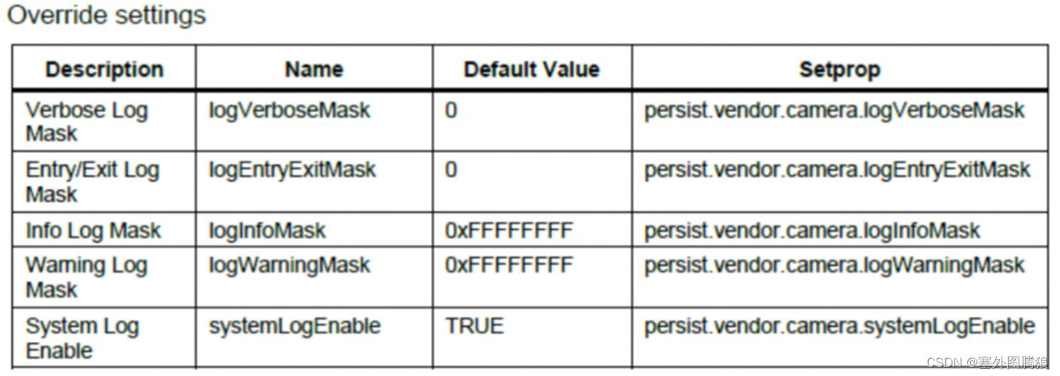
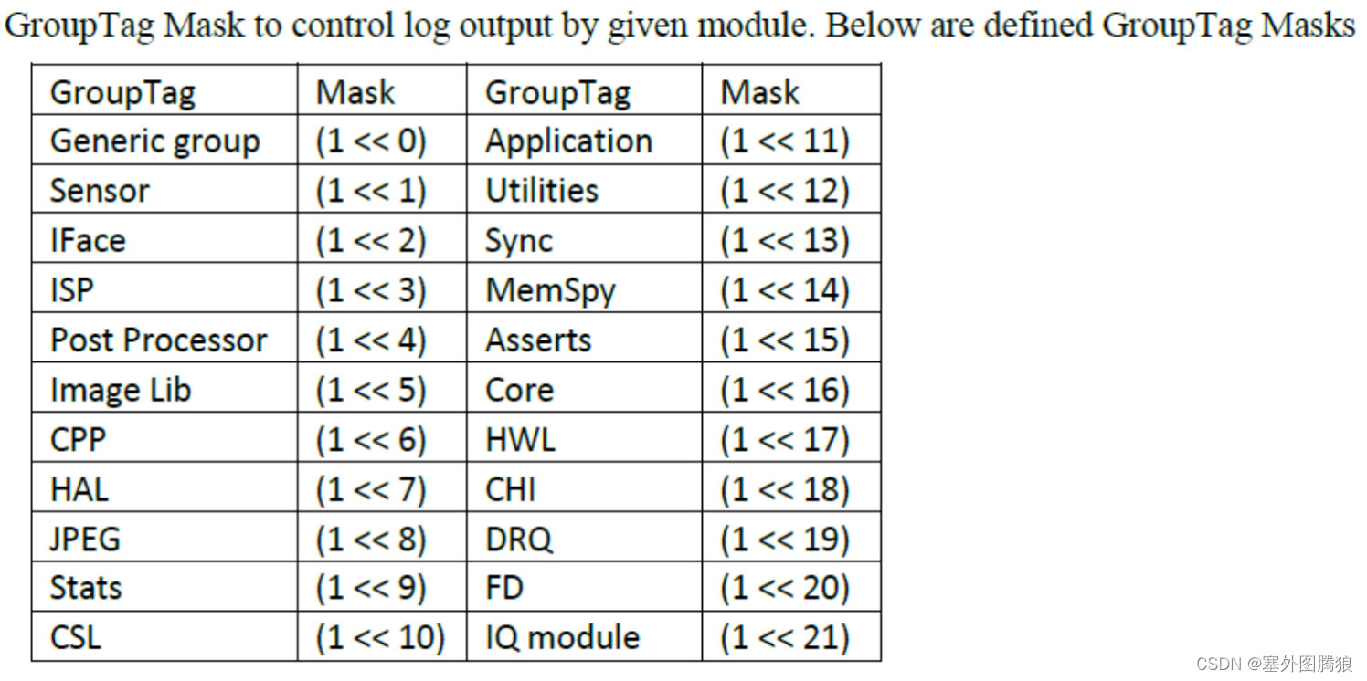
The controlled debug log messages, determines which groups of the camera system will be outputting logs for each log level.
To enable verbose and entry or exit log settings, add the following to the camxoverridesettings.txt file:
logVerboseMask=0xFFFFFFFF
logEntryExitMask=0xFFFFFFFF
Or setting corresponding values to persist.vendor.camera.logVerboseMask persist.vendor.camera.logEntryExitMask
With a rooted device, a quick way to write these values to the override file can be accomplished with the following commands:
adb root
adb remount
adb shell "echo logVerboseMask=0xFFFFFFFF >> /vendor/etc/camera/camxoverridesettings.txt"
adb shell "echo logEntryExitMask=0xFFFFFFFF >> /vendor/etc/camera/camxoverridesettings.txt"
To enable verbose logs only for the HAL CSL groups, enable warnings from sensor, HAL, and CSL, and disable system logging:
logVerboseMask=0x00000480
logWarningMask=0x482
systemLogEnable=FALSE
To enable FPS logs(pre-condition: enable logperflogs, its mask default is 0xFFFFFFFF, which enable perf log info for all modules):
adb shell “echo enableFPSLog=true >> /vendor/etc/camera/camxoverridesettings.txt”
We can also use corresponding property (persist.vendor.camera. enableFPSLog) to set it.
To enable sensor module traces:
adb shell “echo traceGroupEnable=0x2 >> /vendor/etc/camera/camxoverridesettings.txt”
We can also use corresponding property (persist.vendor.camera. traceGroupEnable) to set it.
- UMD logs
The camera driver is implemented with debug log messages. By default, these messages are printed to logcat. The messages can be filtered to limit what is displayed to the user according to their interest (verbosity level and group). Each log comes from a specified group as well as a verbosity level ranging from verbose to error.
NOTE: The example logs used in this document may change over time.
All camera debug logs follow the same format:
CamX: [<Verbosity Level>][<Group>] <File>:<Line Number> <Function Name> <Message>
Example:
CamX: [INFO][CORE] camxexamplefile:123 ExampleFunction()This is the message.
- logs
a block diagram how different Hardware information components are located in SW stack and how those are linked. Black arrows in the picture are presenting the control channels in the SW, red arrows are presenting the hardware information data channels.
Camera kernel mode driver (KMD)
- KMD log messages are enabled by default and appears in the kernel logs. Camera KMD logs all start with the CAM prefix.
Additional debugging logs are available in the KMD and are controlled through groups. See Appendix C A.3 for the full description of the KMD groups.
Example:
To enable CAM_SENSOR and CAM_ICP debug logs in the KMD, run the following commands:
adb root
adb remount
adb shell “echo 0x120 > /sys/module/cam_debug_util/parameters/debug_mdl”
adb shell cat /proc/kmsg > name_of_kmd_logs.txt
- To enable CSID IRQ logs dynamically, use the appropriate mask value(s) using Appendix D A.4 along with the below command:
adb shell “echo MASKVALUE > /sys/kernel/debug/camera_ife/ife_csid_debug”
Example for enabling SOF, EOF, SOT, EOT IRQs:
adb shell “echo 0xf > /sys/kernel/debug/camera_ife/ife_csid_debug”
Example to set the only short packet and long packet capture IRQs:
adb shell “echo 0x30 > /sys/kernel/debug/camera_ife/ife_csid_debug”
The info is logged to kmsg and can be gathered with the command below:
adb shell cat /proc/kmsg > name_of_kmd_logs.txt
- To get the dumps from CSIPHY, use the below command:
adb shell “echo 1 > /sys/module/cam_csiphy_core/parameters/csiphy_dump”
References
1 80-pd126-12 SDM670/710/6150 Linux Android Camera Overview
2 80-pc212-1 CHI API specifications for qualcomm spectra 2xx camera
3 80-P9301-61 F Qualcomm Spectra 2xx Linux Camera Debugging Guide
4 KBA-171129190330 Persist and Property User’s Manual For SDM845/670
5 80-pf777-89_a Camera Quick Start
6 80-p9301-97_c Camera Sensor Driver Bringup Guide
7 kba-171126180135 Camera SDM845/670 Camera Documentation List
8 80-VR556-1 A Camera_v4_HLD_2012_04_18