实验要求如下:

我这里以学号46为例
一、IP 地址规划表
(一)主类网络

(二)子网划分
需要自己计算有效ip范围
在C类主网络192.168.46.0/24中,我们需要先了解这个网络的子网掩码为255.255.255.0,其二进制表示为11111111.11111111.11111111.00000000。这个网络包含了从192.168.46.1到192.168.46.254的可用IP地址。
为了划分出5个子网,我们需要考虑每个子网至少需要2个IP地址(一个用于网络地址,一个用于广播地址),但实际上,为了实际使用,每个子网至少应该分配3个或更多的IP地址(一个用于网络地址,一个用于广播地址,一个或更多用于主机)。
如果我们假设每个子网至少需要4个IP地址(出于简化的考虑),我们可以从主机位中借用3位来划分子网。这样,我们可以得到2^3 = 8个子网掩码块,子网掩码/24 就变为 /27(255.255.255.224)(二进制: 11111111.11111111.11111111.11100000)了可以划分成 8 个子网,每个子网有 32 个地址,其中 30 个是有效的主机地址,但我们只需要5个子网掩码块,够用了。
有效IP范围 |
子网掩码 |
网络地址 |
广播地址 |
||
| 企业网1 |
VLAN-2 |
192.168.46.1 - 192.168.46.30 |
255.255.255.224 |
192.168.46.0 |
192.168.46.31 |
VLAN-3 |
192.168.46.33 - 192.168.46.62 |
255.255.255.224 |
192.168.46.32 |
192.168.46.63 |
|
| 企业网2 |
VLAN-2 |
192.168.46.65 - 192.168.46.94 |
255.255.255.224 |
192.168.46.64 |
192.168.46.95 |
VLAN-3 |
192.168.46.97 - 192.168.46.126 |
255.255.255.224 |
192.168.46.96 |
192.168.46.127 |
|
路由器 |
直连链路 |
192.168.46.129 - 192.168.46.158 |
255.255.255.224 |
192.168.46.128 |
192.168.46.159 |
(三)IP分配表
IP地址 |
子网掩码 |
网关地址 |
|||
| 企业网1 |
VLAN-2 |
PC0 |
192.168.46.2 |
255.255.255.224 |
192.168.46.1 |
PC1 |
192.168.46.3 |
255.255.255.224 |
192.168.46.1 |
||
| VLAN-3 |
PC2 |
192.168.46.34 |
255.255.255.224 |
192.168.46.33 |
|
PC3 |
192.168.46.35 |
255.255.255.224 |
192.168.46.33 |
||
| 企业网2 |
VLAN-2 |
PC4 |
192.168.46.66 |
255.255.255.224 |
192.168.46.65 |
PC5 |
192.168.46.67 |
255.255.255.224 |
192.168.46.65 |
||
| VLAN-3 |
PC6 |
192.168.46.98 |
255.255.255.224 |
192.168.46.97 |
|
PC7 |
192.168.46.99 |
255.255.255.224 |
192.168.46.97 |
||
| 路由器1 |
VLAN-2子接口 |
192.168.46.1 |
255.255.255.224 |
- |
|
VLAN-3子接口 |
192.168.46.33 |
255.255.255.224 |
- |
||
与路由器2互联端口 |
192.168.46.129 |
255.255.255.224 |
- |
||
| 路由器2 |
VLAN-2子接口 |
192.168.46.65 |
255.255.255.224 |
- |
|
VLAN-3子接口 |
192.168.46.97 |
255.255.255.224 |
- |
||
与路由器1互联端口 |
192.168.46.130 |
255.255.255.224 |
- |
||
(四)VLAN端口分配表
VLAN名称(ID) |
端口分配 |
|
企业网1 |
VLAN-2 |
fa0/0, fa0/1 |
VLAN-3 |
fa0/2,fa 0/3 |
|
企业网2 |
VLAN-2 |
fa0/4,fa 0/5 |
VLAN-3 |
fa0/6, fa0/7 |
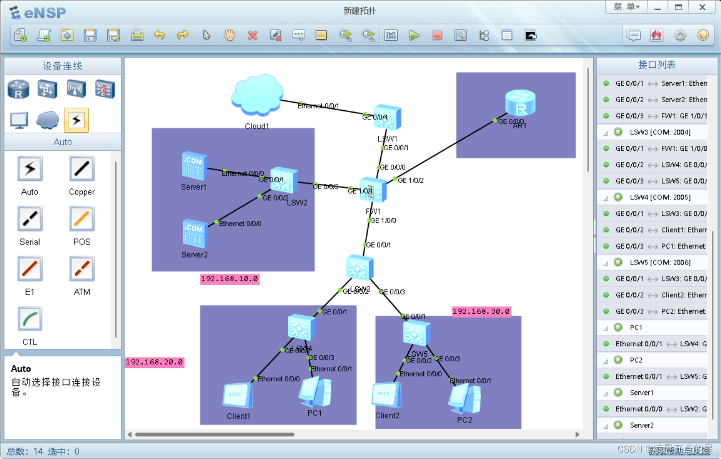
二、网络拓扑及参数规划图

我方便使用后面的指令请注意连接方向和顺序

ctrl+r勾选显示端口(ip地址什么的是我自己手动写的不用管)
 配置每个电脑的ip地址、子网掩码、网关地址
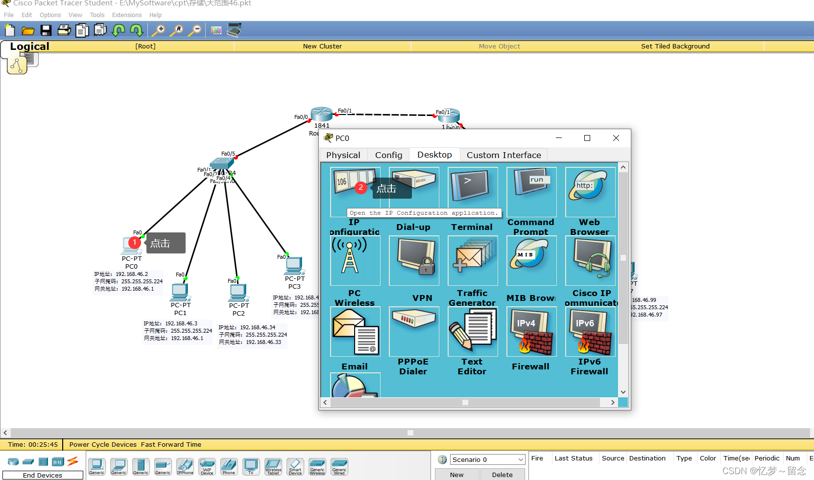

交换机VLAN配置
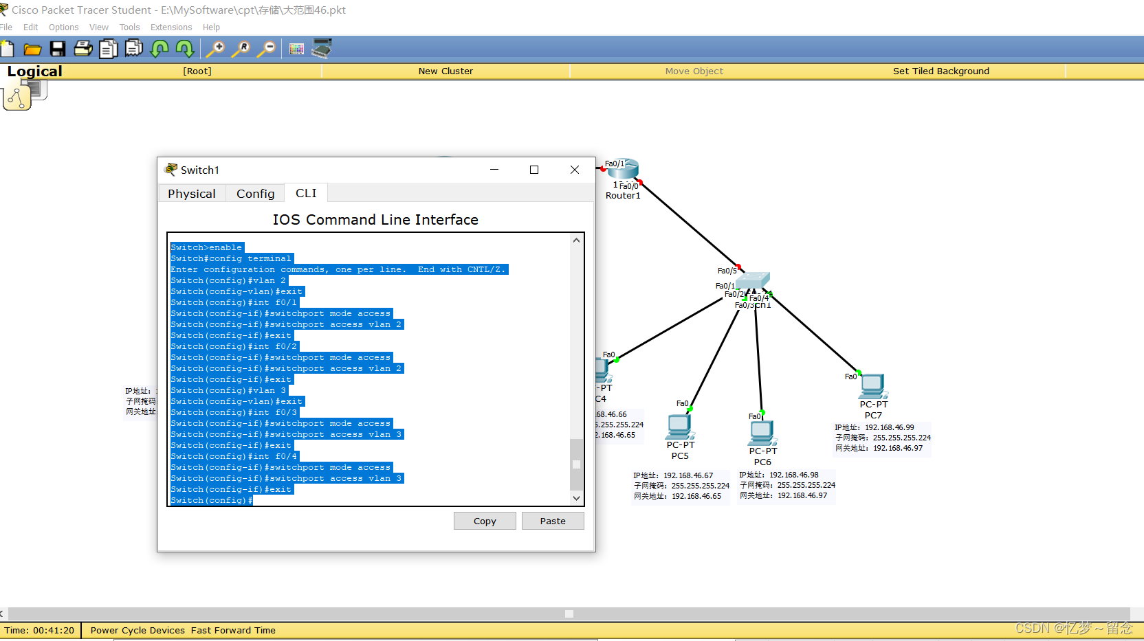
左边交换机(注意:指令中有关的ip都是自己表中对应的ip)

Switch>enable
Switch#config terminal
Enter configuration commands, one per line.  End with CNTL/Z.
Switch(config)#vlan 2
Switch(config-vlan)#exit
Switch(config)#int f0/1
Switch(config-if)#switchport mode access
Switch(config-if)#switchport access vlan 2
Switch(config-if)#exit
Switch(config)#int f0/2
Switch(config-if)#switchport mode access
Switch(config-if)#switchport access vlan 2
Switch(config-if)#exit
Switch(config)#vlan 3
Switch(config-vlan)#exit
Switch(config)#int f0/3
Switch(config-if)#switchport mode access
Switch(config-if)#switchport access vlan 3
Switch(config-if)#exit
Switch(config)#int f0/4
Switch(config-if)#switchport mode access
Switch(config-if)#switchport access vlan 3
Switch(config-if)#exit
Switch(config)#int f0/5
Switch(config-if)#switchport mode trunk
Switch(config-if)#上面指令提取出来如下
enable
config terminal
vlan 2
exit
int f0/1
switchport mode access
switchport access vlan 2
exit
int f0/2
switchport mode access
switchport access vlan 2
exit
vlan 3
exit
int f0/3
switchport mode access
switchport access vlan 3
exit
int f0/4
switchport mode access
switchport access vlan 3
exit
int f0/5
switchport mode trunk
右边交换机
Switch>enable
Switch#config terminal
Enter configuration commands, one per line.  End with CNTL/Z.
Switch(config)#vlan 2
Switch(config-vlan)#exit
Switch(config)#int f0/1
Switch(config-if)#switchport mode access
Switch(config-if)#switchport access vlan 2
Switch(config-if)#exit
Switch(config)#int f0/2
Switch(config-if)#switchport mode access
Switch(config-if)#switchport access vlan 2
Switch(config-if)#exit
Switch(config)#vlan 3
Switch(config-vlan)#exit
Switch(config)#int f0/3
Switch(config-if)#switchport mode access
Switch(config-if)#switchport access vlan 3
Switch(config-if)#exit
Switch(config)#int f0/4
Switch(config-if)#switchport mode access
Switch(config-if)#switchport access vlan 3
Switch(config-if)#exit
Switch(config)#
Switch(config)#int f0/5
Switch(config-if)#switchport mode trunk
Switch(config-if)#上面指令提取出来如下
enable
config terminal
vlan 2
exit
int f0/1
switchport mode access
switchport access vlan 2
exit
int f0/2
switchport mode access
switchport access vlan 2
exit
vlan 3
exit
int f0/3
switchport mode access
switchport access vlan 3
exit
int f0/4
switchport mode access
switchport access vlan 3
exit

int f0/5
switchport mode trunk
单臂路由配置
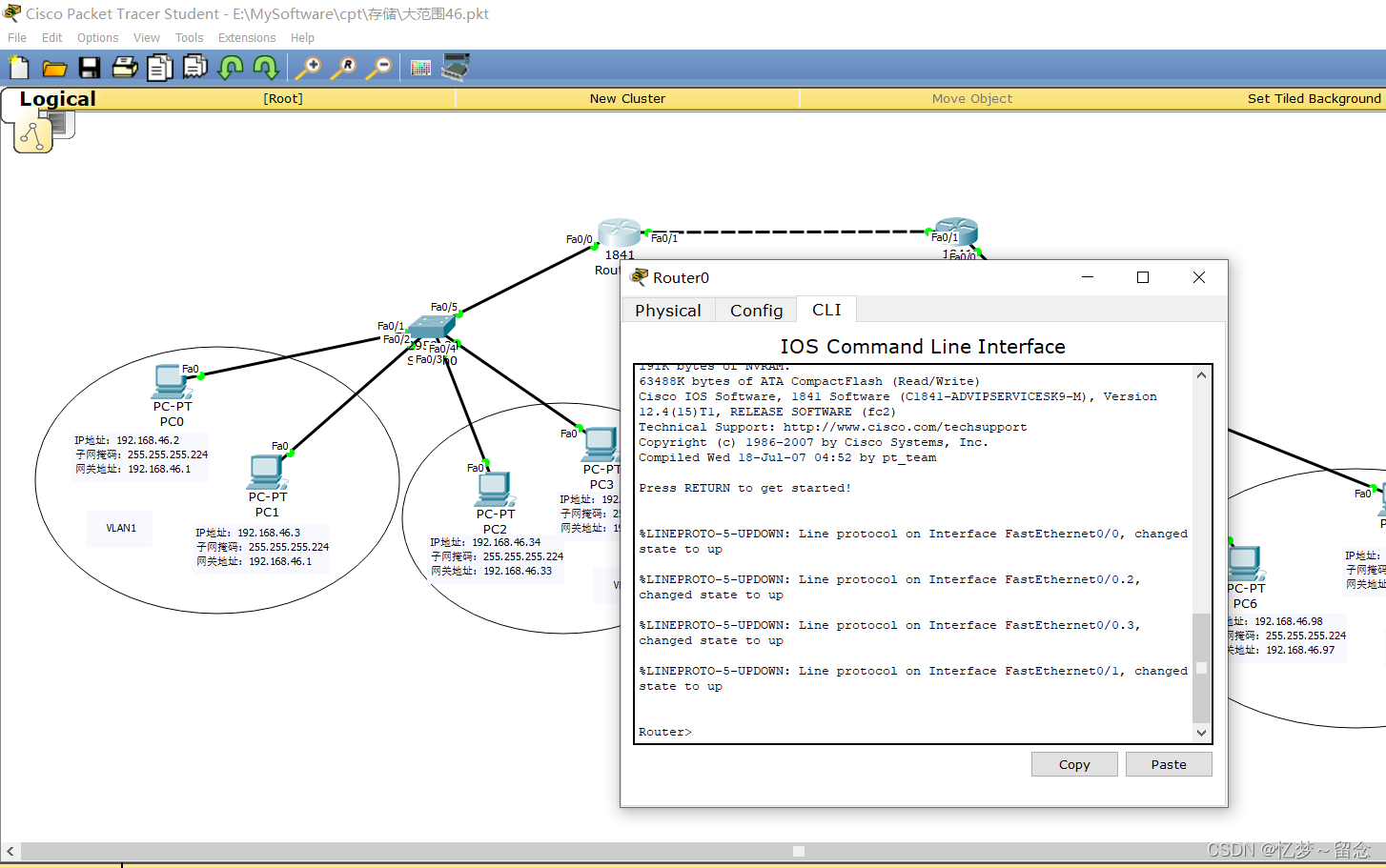
左路由(其中涉及的地址写你自己路由器1的VLAN子接口的IP地址和子网掩码)
Router>en
Router#config terminal
Enter configuration commands, one per line.  End with CNTL/Z.
Router(config)#int fa0/0
Router(config-if)#no shutdown

Router(config-if)#
%LINK-5-CHANGED: Interface FastEthernet0/0, changed state to up

%LINEPROTO-5-UPDOWN: Line protocol on Interface FastEthernet0/0, changed state to up

Router(config-if)#int fa0/0.2
Router(config-subif)#
%LINK-5-CHANGED: Interface FastEthernet0/0.2, changed state to up

%LINEPROTO-5-UPDOWN: Line protocol on Interface FastEthernet0/0.2, changed state to up

Router(config-subif)#encapsulation dot1Q 2
Router(config-subif)#ip add 192.168.46.1 255.255.255.224
Router(config-subif)#int fa0/0.3
Router(config-subif)#
%LINK-5-CHANGED: Interface FastEthernet0/0.3, changed state to up

%LINEPROTO-5-UPDOWN: Line protocol on Interface FastEthernet0/0.3, changed state to up

Router(config-subif)#encapsulation dot1Q 3
Router(config-subif)#ip add 192.168.46.33 255.255.255.224
Router(config-subif)#
上面指令提取出来如下
en
config terminal
int fa0/0
no shutdown
int fa0/0.2
encapsulation dot1Q 2
ip add 192.168.46.1 255.255.255.224
int fa0/0.3
encapsulation dot1Q 3
ip add 192.168.46.33 255.255.255.224
右边路由

Router>en
Router#config terminal
Enter configuration commands, one per line.  End with CNTL/Z.
Router(config)#int fa0/0
Router(config-if)#no shutdown

Router(config-if)#
%LINK-5-CHANGED: Interface FastEthernet0/0, changed state to up

%LINEPROTO-5-UPDOWN: Line protocol on Interface FastEthernet0/0, changed state to up

Router(config-if)#int fa0/0.2
Router(config-subif)#
%LINK-5-CHANGED: Interface FastEthernet0/0.2, changed state to up

%LINEPROTO-5-UPDOWN: Line protocol on Interface FastEthernet0/0.2, changed state to up

Router(config-subif)#encapsulation dot1Q 2
Router(config-subif)#ip add 192.168.46.65 255.255.255.224
Router(config-subif)#int fa0/0.3
Router(config-subif)#
%LINK-5-CHANGED: Interface FastEthernet0/0.3, changed state to up

%LINEPROTO-5-UPDOWN: Line protocol on Interface FastEthernet0/0.3, changed state to up

Router(config-subif)#encapsulation dot1Q 3
Router(config-subif)#ip add 192.168.46.97 255.255.255.224
Router(config-subif)#
上面指令提取出来如下
en
config terminal
int fa0/0
no shutdown
int fa0/0.2
encapsulation dot1Q 2
ip add 192.168.46.65 255.255.255.224
int fa0/0.3
encapsulation dot1Q 3
ip add 192.168.46.97 255.255.255.224
静态路由配置
(ip add 本路由器地址 子网掩码)
(ip route 目标地址 子网掩码 下一跳)
左边路由
Router>en
Router#config terminal
Enter configuration commands, one per line.  End with CNTL/Z.
Router(config)#int fa0/1
Router(config-if)#ip address 192.168.46.129 255.255.255.224
Router(config-if)#no shutdown
Router(config-if)#
%LINK-5-CHANGED: Interface FastEthernet0/1, changed state to up
Router(config-if)#ip route 192.168.46.96 255.255.255.224 192.168.46.130
Router(config)#int fa0/1
Router(config-if)#ip route 192.168.46.64 255.255.255.224 192.168.46.130
Router(config)#
上面指令提取出来如下
en
config terminal
int fa0/1
ip address 192.168.46.129 255.255.255.224
no shutdown
ip route 192.168.46.96 255.255.255.224 192.168.46.130
int fa0/1
ip route 192.168.46.64 255.255.255.224 192.168.46.130
右边路由
Router>en
Router#config terminal
Enter configuration commands, one per line.  End with CNTL/Z.
Router(config)#int fa0/1
Router(config-if)#ip address 192.168.46.130 255.255.255.224
Router(config-if)#ip route 192.168.46.0 255.255.255.224 192.168.46.129
Router(config)#int fa0/1
Router(config-if)#ip route 192.168.46.32 255.255.255.224 192.168.46.129
Router(config)#int fa0/1
Router(config-if)#no shutdown

Router(config-if)#
%LINK-5-CHANGED: Interface FastEthernet0/1, changed state to up

%LINEPROTO-5-UPDOWN: Line protocol on Interface FastEthernet0/1, changed state to up

Router(config-if)#
上面指令提取出来如下
en
config terminal
int fa0/1
ip address 192.168.46.130 255.255.255.224
ip route 192.168.46.0 255.255.255.224 192.168.46.129
int fa0/1
ip route 192.168.46.32 255.255.255.224 192.168.46.129
int fa0/1
no shutdown
三、交换机配置图
(一)VLAN配置
1、交换机1的VLAN配置图
show vlan brief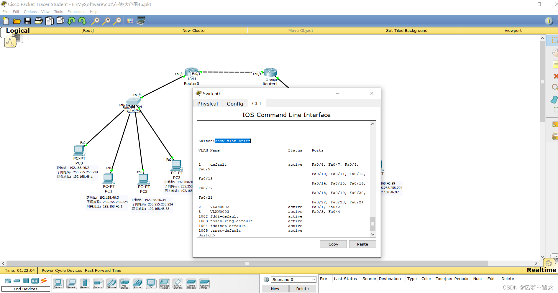
2、交换机2的VLAN配置图
show vlan brief 
(二)TRUNK配置
1、交换机1接口的TRUNK状态图
show interface trunk
2、交换机2的VLAN配置图
show interface trunk
四、路由器配置图
(一)路由器1
1、路由器1端口配置图
show ip interface brief 2、路由器1的静态路由表项
show ip interface brief
(二)路由器2
1、路由器2端口配置图
show ip route 2、路由器2的静态路由表项
show ip route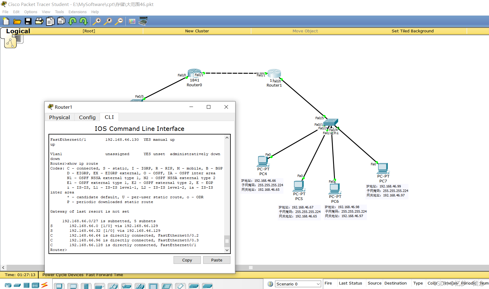 五、Ping通图

实验报告其他部分
实验项目 |
实验3:小型企业网络组网与配置仿真实验 |
类别 |
验证性 |
£ |
实验目的 |
1.掌握配置交换机VLAN和TRUNK链路的基本方法和步骤; 2.掌握规划和配置路由器接口IP地址的基本方法; 3.掌握在路由器上配置单臂路由实现VLAN间通信的基本方法。 |
|||
实验任务与要求 |
1.在Packet Tracer模拟环境下搭建一个小型企业网络; 2.规划并配置网络的IP参数、VLAN、TRUNK链路和单臂路由; 3.测试网络的连通性。 |
|||
实验原理(技术) |
小型企业网络组网与配置仿真实验通过单臂路由、VLAN划分、静态路由配置实现不同VLAN之间的通信。 单臂路由:在路由器的一个接口上通过配置子接口(逻辑接口)的方式,实现原来相互隔离的不同VLAN之间的互联互通。 VLAN(Virtual LAN,虚拟局域网):在交换式局域网的基础上,对连接到的第二层交换机端口的网络用户进行逻辑分组,不受网络用户物理位置的限制。各个VLAN逻辑分组之间彼此隔离,互相不能访问,不仅实现了广播域的分隔,而且增强了网络的安全性。 路由器不同接口的IP不能位于同一网段;路由器连接内网的网关接口IP应该与内网IP位于同一网段;路由器直连链路两端的IP应该位于同一网段。 |
|||
实验仪器设备(环境条件) |
硬件环境:PC终端或笔记本电脑一台 软件环境:Windows操作系统和PT模拟软件 |
|||