目录
2.2.3 include/linux/gpio.h 全部代码
2.4.2/sys/kernel/debug/gpio/pinctrl
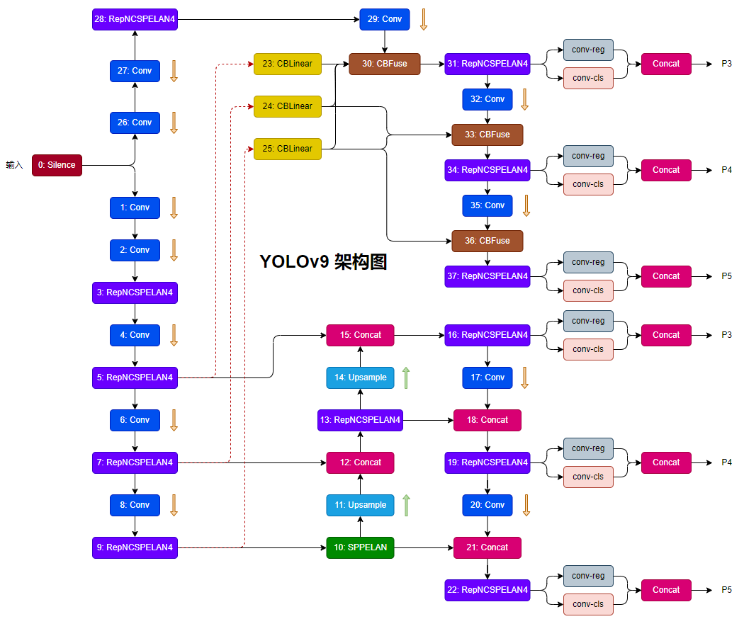
1 GPIO整体架构
从Linux kernel 2.6.24开始,GPIO控制核心就通过gpiolib来进行实现了。
gpiolib初始提交信息:
gpiolib: add gpio provider infrastructure - kernel/git/torvalds/linux.git - Linux kernel source tree
gpiolib初始提交代码:
gpiolib.c « gpio « drivers - kernel/git/torvalds/linux.git - Linux kernel source tree
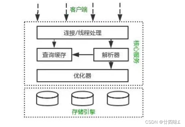
关于gpio的使用block图如下:
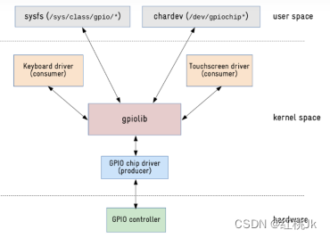
对于hardware层:
- GPIO controller是硬件物理结构
对于kernel space层:
- 芯片厂商的bsp工程师负责gpio chip driver
- 开源社区(linux kernel)的大佬负责gpiolib的核心功能实现
- BSP开发担当负责编写gpio consumer driver,可以从kernel driver中控制gpio
对于user space层:
- APP开发担当可以从user space 使用sysfs和chardev的形式控制gpio
因此正常情况下,BSP及APP开发不需要深入GPIO chip driver和gpiolib,仅了解其使用方式即可
2 user space 层 gpio使用方法
2.1 sysfs控制方法
查看kernel版本中关于gpiofs的官方描述,可以通过kernel官网
网址:kernel.org/doc/Documentation/gpio/sysfs.txt
2.1.1 kernel版本区别
上述网站中最新的描述中可以看到gpio sysfs已经弃用了

查看相关资料时发现,这个改动是从2015年逐渐从linux kernel4.6开始引入的,至到4.8版本(2020年)正式废弃。这部分的提交代码如下:
所以在kernel4.8以前可以直接使用gpio sysfs的方法来控制gpio。
如果在4.8以后,想要再使用这个接口,可以通过改变menuconfig的方式打开CONFIG_GPIO_SYSFS,然后就可以继续使用gpio sysfs来控制gpio了。

2.1.2 /sys/class/gpio
该目录下的gpio可以直接通过命令进行操作。

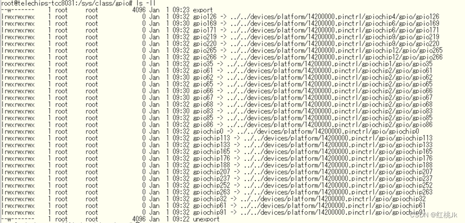
该目录下有个export文件,向export文件写入要操作的GPIO号,使得该GPIO的操作接口从内核空间暴露到用户空间,GPIO的操作接口包括direction和value等,direction控制GPIO输入或者输出模式,而value可控制GPIO的状态或者读取状态。
/sys/class/gpio/目录下各个文件说明:
/sys/class/gpio/export文件用于通知系统需要导出控制的GPIO引脚编号;
/sys/class/gpio/unexport 用于通知系统取消导出;
/sys/class/gpio/gpioX/direction文件,可以通过echo写入in(设置输入方向)或out(设置输出方向);通过cat读出输入方向
/sys/class/gpio/gpioX/value文件是可以读写GPIO状态;echo 写入,cat读出
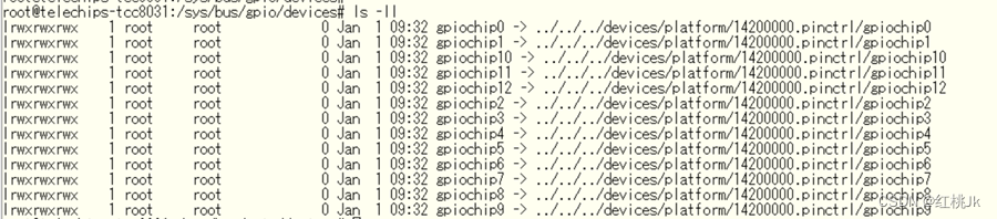
/sys/class/gpio/gpiochipX目录保存系统中GPIO寄存器的信息,包括每个寄存器控制引脚的起始编号,寄存器名称,引脚总数;其中X表示具体的引脚编号。
对于组别和编号的判断,在此目录下使用命令: for file in ./gpiochip*/label;do echo -n "$file ------->";cat "$file";done; 可以确认端子组别信息
效果如下:

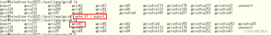
上述内容gpc对应的gpio起始编号为61,如果此时想要操作gpc_0,则对应编号则为61+0=61
使用echo 61 > export则可以导出gpc_0的端子文件目录
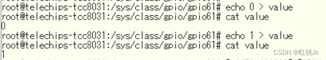
进入gpio61 目录后可以通过 cat 获取当前gpio的电平状态和输入输出状态,也可以通过echo命令 改变gpio输出的电平状态
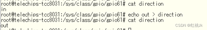
通过echo和cat命令 确认gpio输入输出模式
上述的控制台命令在app的代码上可以使用system函数取代例如:
void GPIO_LOW_SET(void)
{
    system("echo 247 > /sys/class/gpio/export");
    system("echo out > /sys/class/gpio/gpio247/direction");
    system("echo 0 > /sys/class/gpio/gpio247/value");

    system("echo 248 > /sys/class/gpio/export");
    system("echo out > /sys/class/gpio/gpio248/direction");
    system("echo 0 > /sys/class/gpio/gpio248/value");

    system("echo 249 > /sys/class/gpio/export");
    system("echo out > /sys/class/gpio/gpio249/direction");
    system("echo 0 > /sys/class/gpio/gpio249/value");

}
2.1.3 /sys/bug/gpio/devices
确认gpio组别不仅可以通过上述 /gpio/class/gpio/gpiochip*/label 取得。
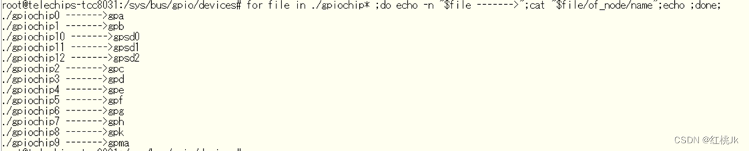
还可以通过 /sys/bus/gpio/devices/gpiochip* /of_node/name 取得
在/sys/bus/gpio/devices目录下使用命令:
for file in ./gpiochip* ;do echo -n "$file ------->";cat "$file/of_node/name";echo ;done;结果效果:

其实/sys/bus/gpio/devices和/sys/class/gpio的区别到底在哪呢?在此不详细说明,通过下面的内容也许能为你提供一些灵感。(下图可能也表明了/sys/bus和/sys/class的一些奥妙!)
/sys/bus/gpio/devices
/sys/class/gpio
2.2 chardev控制方法
通过【1gpio整体架构】的block图可以看到主要使用的节点是/dev/gpiochip*,这是一个设备节点。对于app的开发,应当使用open,ioctl,write,read等文件接口对它进行操作。
可操作的设备 在/dev下都命名为gpiochip* 如下图:
![]()
相关libgpiod网页:libgpiod/libgpiod.git - C library and tools for interacting with the linux GPIO character device (kernel.org)
2.2.1 chardev 示例代码
下面是一段用于拉高gpiochip4_4的示例代码
#include <linux/gpio.h>
#define HIGH                        (1)
#define LOW                         (0)
#define RES_NG                      (1)
#define RES_OK                      (0)
#define INIT_STATUS_LINES 4
#define  INIT_STATUS_GPIOCHIPS "/dev/gpiochip4"

/********************************************************************************/
/* Function Name        : nswWrite_PowerGPIO_Value                              */
/* Date                 : 2024/01/11                                            */
/* Author               : HeartJoKer                                            */
/* Description          : Set Power Gpio:INIT_STATE Value                       */
/* Argument Code        : none                                                  */
/* Return Code          : Type_sWord    aswRet 0 is OK,1 is NG                  */
/* Tips                 : GPIO 相关宏及结构体定义参考/include/linux/gpio.h       */
/*------------------------------------------------------------------------------*/
/* Revision History                                                             */
/* No.        Date                  Revised by          Function Name           */
/* 0001    2024/01/11               HeartJoKer            New                   */
/********************************************************************************/
Type_sWord nswWrite_PowerGPIO_Value()
{
    Type_sWord aswRet = RES_NG;
    Type_sWord aswLineFd = 0;
    Type_sWord aswChipFd = 0;
    struct gpiohandle_data astData;
    struct gpiohandle_request astreq;
    memset(&astData,0,sizeof(astData));
    memset(&astreq,0,sizeof(astreq));
    ALOGI("Start to Set GPIO:INIT_STATUS Vaule");
    aswChipFd = open(INIT_STATUS_GPIOCHIPS, 0);
    if(aswChipFd < 0){
        ALOGI("OPEN /dev/GpioChip4 Error, errnor = %d; strerror = %s",errno,strerror(errno));
        aswRet = RES_NG;
    }else{
        astreq.lineoffset[0] = INIT_STATUS_LINES;
        astreq.lines = 1;           // 仅设定INIT_STATUS一个端子所以为1
        astreq.flags = GPIOHANDLE_REQUEST_OUTPUT;  //设定为OUTPUT模式
        strcpy(req.consumer_label, "dAndroid_Power_HAL");  //记录使用者信息
        aswRet = ioctl(aswChipFd, GPIO_GET_LINEHANDLE_IOCTL, &astreq);
        if(aswRet < 0){
            ALOGI("Get INIT_STATUS GpioLineHandle error, errnor = %d; strerror = %s",errno,strerror(errno)); //无法获取GPIO_CHIP_LINE句柄信息
            aswRet = RES_NG;
        }else{
            astData.values[0] = HIGH; // 想要设定的电平 HIGH or LOW
            if(astreq.fd < 0){
                ALOGI("INIT_STATUS GpioLineHandle return fd error");//无法获取GPIO_CHIP_LINE的句柄赋值信息
                aswRet = RES_NG;
            }else{
                aswRet = ioctl(astreq.fd, GPIOHANDLE_SET_LINE_VALUES_IOCTL, &astData);
                if(aswRet < 0){
                    ALOGI("Set INIT_STATUS Vaule:[%d] error, errnor = %d; strerror = %s",astData.values[0],errno,strerror(errno));
                    aswRet = RES_NG;
                }else{
                    ALOGI("Set INIT_STATUS Vaule:[%d] sucess ",astData.values[0]);
                    aswRet = RES_OK;
                }
            }
        }
        close(aswChipFd);
    }
    return aswRet;
}
2.2.2 示例代码主要步骤描述
其中有四步关键内容
①open(INIT_STATUS_GPIOCHIPS, 0);
②ioctl(aswChipFd, GPIO_GET_LINEHANDLE_IOCTL, &astreq)
③ioctl(astreq.fd, GPIOHANDLE_SET_LINE_VALUES_IOCTL, &astData)
④ close(aswChipFd)
再提及这四个具体步骤之前,要明确两个概念
概念一:gpiochip_group:参照上文提到的gpiochip,对应不同gpio组,例如:
概念二:gpiochip_group_line:对应每一个gpiochip_group每一组下的每一个gpio
结合上述两个概念,gpioe-4,即/dev/gpiochip4--->line4
明确上述概念后,上述代码的四步逻辑就能比较清晰的理解
①选择gpiochip,通过open函数获取对应dev的Fd句柄
②通过ioctl获取对应Line句柄
③通过ioctl上述选择的Line进行操作
④关闭dev设备
对于②③可用的ioctrl宏参照如下:(include/linux/gpio.h)
/*
 * v1 and v2 ioctl()s
 */
#define GPIO_GET_CHIPINFO_IOCTL _IOR(0xB4, 0x01, struct gpiochip_info)
#define GPIO_GET_LINEINFO_UNWATCH_IOCTL _IOWR(0xB4, 0x0C, __u32)

/*
 * v2 ioctl()s
 */
#define GPIO_V2_GET_LINEINFO_IOCTL _IOWR(0xB4, 0x05, struct gpio_v2_line_info)
#define GPIO_V2_GET_LINEINFO_WATCH_IOCTL _IOWR(0xB4, 0x06, struct gpio_v2_line_info)
#define GPIO_V2_GET_LINE_IOCTL _IOWR(0xB4, 0x07, struct gpio_v2_line_request)
#define GPIO_V2_LINE_SET_CONFIG_IOCTL _IOWR(0xB4, 0x0D, struct gpio_v2_line_config)
#define GPIO_V2_LINE_GET_VALUES_IOCTL _IOWR(0xB4, 0x0E, struct gpio_v2_line_values)
#define GPIO_V2_LINE_SET_VALUES_IOCTL _IOWR(0xB4, 0x0F, struct gpio_v2_line_values)

/*
 * v1 ioctl()s
 *
 * These ioctl()s are deprecated.  Use the v2 equivalent instead.
 */
#define GPIO_GET_LINEINFO_IOCTL _IOWR(0xB4, 0x02, struct gpioline_info)
#define GPIO_GET_LINEHANDLE_IOCTL _IOWR(0xB4, 0x03, struct gpiohandle_request)
#define GPIO_GET_LINEEVENT_IOCTL _IOWR(0xB4, 0x04, struct gpioevent_request)
#define GPIOHANDLE_GET_LINE_VALUES_IOCTL _IOWR(0xB4, 0x08, struct gpiohandle_data)
#define GPIOHANDLE_SET_LINE_VALUES_IOCTL _IOWR(0xB4, 0x09, struct gpiohandle_data)
#define GPIOHANDLE_SET_CONFIG_IOCTL _IOWR(0xB4, 0x0A, struct gpiohandle_config)
#define GPIO_GET_LINEINFO_WATCH_IOCTL _IOWR(0xB4, 0x0B, struct gpioline_info)
使用这些宏时需要关注其相关结构体,例如上文中使用
②GPIO_GET_LINEHANDLE_IOCTL----> gpiohandle_request
对应结构体
/**
 * struct gpiohandle_request - Information about a GPIO handle request
 * @lineoffsets: an array of desired lines, specified by offset index for the
 * associated GPIO device
 * @flags: desired flags for the desired GPIO lines, such as
 * %GPIOHANDLE_REQUEST_OUTPUT, %GPIOHANDLE_REQUEST_ACTIVE_LOW etc, added
 * together. Note that even if multiple lines are requested, the same flags
 * must be applicable to all of them, if you want lines with individual
 * flags set, request them one by one. It is possible to select
 * a batch of input or output lines, but they must all have the same
 * characteristics, i.e. all inputs or all outputs, all active low etc
 * @default_values: if the %GPIOHANDLE_REQUEST_OUTPUT is set for a requested
 * line, this specifies the default output value, should be 0 (low) or
 * 1 (high), anything else than 0 or 1 will be interpreted as 1 (high)
 * @consumer_label: a desired consumer label for the selected GPIO line(s)
 * such as "my-bitbanged-relay"
 * @lines: number of lines requested in this request, i.e. the number of
 * valid fields in the above arrays, set to 1 to request a single line
 * @fd: if successful this field will contain a valid anonymous file handle
 * after a %GPIO_GET_LINEHANDLE_IOCTL operation, zero or negative value
 * means error
 *
 * Note: This struct is part of ABI v1 and is deprecated.
 * Use &struct gpio_v2_line_request instead.
 */
struct gpiohandle_request {
	__u32 lineoffsets[GPIOHANDLES_MAX];
	__u32 flags;
	__u8 default_values[GPIOHANDLES_MAX];
	char consumer_label[GPIO_MAX_NAME_SIZE];
	__u32 lines;
	int fd;
};③GPIOHANDLE_SET_LINE_VALUES_IOCTL -> gpiohandle_data
对应结构体描述
/**
 * struct gpiohandle_data - Information of values on a GPIO handle
 * @values: when getting the state of lines this contains the current
 * state of a line, when setting the state of lines these should contain
 * the desired target state
 *
 * Note: This struct is part of ABI v1 and is deprecated.
 * Use &struct gpio_v2_line_values instead.
 */
struct gpiohandle_data {
	__u8 values[GPIOHANDLES_MAX];
};
2.2.3 include/linux/gpio.h 全部代码
gpio.h整体内容如下 ,可以详细了解:
/* SPDX-License-Identifier: GPL-2.0-only WITH Linux-syscall-note */
/*
 * <linux/gpio.h> - userspace ABI for the GPIO character devices
 *
 * Copyright (C) 2016 Linus Walleij
 *
 * This program is free software; you can redistribute it and/or modify it
 * under the terms of the GNU General Public License version 2 as published by
 * the Free Software Foundation.
 */
#ifndef _UAPI_GPIO_H_
#define _UAPI_GPIO_H_

#include <linux/const.h>
#include <linux/ioctl.h>
#include <linux/types.h>

/*
 * The maximum size of name and label arrays.
 *
 * Must be a multiple of 8 to ensure 32/64-bit alignment of structs.
 */
#define GPIO_MAX_NAME_SIZE 32

/**
 * struct gpiochip_info - Information about a certain GPIO chip
 * @name: the Linux kernel name of this GPIO chip
 * @label: a functional name for this GPIO chip, such as a product
 * number, may be empty (i.e. label[0] == '\0')
 * @lines: number of GPIO lines on this chip
 */
struct gpiochip_info {
	char name[GPIO_MAX_NAME_SIZE];
	char label[GPIO_MAX_NAME_SIZE];
	__u32 lines;
};

/*
 * Maximum number of requested lines.
 *
 * Must be no greater than 64, as bitmaps are restricted here to 64-bits
 * for simplicity, and a multiple of 2 to ensure 32/64-bit alignment of
 * structs.
 */
#define GPIO_V2_LINES_MAX 64

/*
 * The maximum number of configuration attributes associated with a line
 * request.
 */
#define GPIO_V2_LINE_NUM_ATTRS_MAX 10

/**
 * enum gpio_v2_line_flag - &struct gpio_v2_line_attribute.flags values
 * @GPIO_V2_LINE_FLAG_USED: line is not available for request
 * @GPIO_V2_LINE_FLAG_ACTIVE_LOW: line active state is physical low
 * @GPIO_V2_LINE_FLAG_INPUT: line is an input
 * @GPIO_V2_LINE_FLAG_OUTPUT: line is an output
 * @GPIO_V2_LINE_FLAG_EDGE_RISING: line detects rising (inactive to active)
 * edges
 * @GPIO_V2_LINE_FLAG_EDGE_FALLING: line detects falling (active to
 * inactive) edges
 * @GPIO_V2_LINE_FLAG_OPEN_DRAIN: line is an open drain output
 * @GPIO_V2_LINE_FLAG_OPEN_SOURCE: line is an open source output
 * @GPIO_V2_LINE_FLAG_BIAS_PULL_UP: line has pull-up bias enabled
 * @GPIO_V2_LINE_FLAG_BIAS_PULL_DOWN: line has pull-down bias enabled
 * @GPIO_V2_LINE_FLAG_BIAS_DISABLED: line has bias disabled
 * @GPIO_V2_LINE_FLAG_EVENT_CLOCK_REALTIME: line events contain REALTIME timestamps
 */
enum gpio_v2_line_flag {
	GPIO_V2_LINE_FLAG_USED			= _BITULL(0),
	GPIO_V2_LINE_FLAG_ACTIVE_LOW		= _BITULL(1),
	GPIO_V2_LINE_FLAG_INPUT			= _BITULL(2),
	GPIO_V2_LINE_FLAG_OUTPUT		= _BITULL(3),
	GPIO_V2_LINE_FLAG_EDGE_RISING		= _BITULL(4),
	GPIO_V2_LINE_FLAG_EDGE_FALLING		= _BITULL(5),
	GPIO_V2_LINE_FLAG_OPEN_DRAIN		= _BITULL(6),
	GPIO_V2_LINE_FLAG_OPEN_SOURCE		= _BITULL(7),
	GPIO_V2_LINE_FLAG_BIAS_PULL_UP		= _BITULL(8),
	GPIO_V2_LINE_FLAG_BIAS_PULL_DOWN	= _BITULL(9),
	GPIO_V2_LINE_FLAG_BIAS_DISABLED		= _BITULL(10),
	GPIO_V2_LINE_FLAG_EVENT_CLOCK_REALTIME	= _BITULL(11),
};

/**
 * struct gpio_v2_line_values - Values of GPIO lines
 * @bits: a bitmap containing the value of the lines, set to 1 for active
 * and 0 for inactive.
 * @mask: a bitmap identifying the lines to get or set, with each bit
 * number corresponding to the index into &struct
 * gpio_v2_line_request.offsets.
 */
struct gpio_v2_line_values {
	__aligned_u64 bits;
	__aligned_u64 mask;
};

/**
 * enum gpio_v2_line_attr_id - &struct gpio_v2_line_attribute.id values
 * identifying which field of the attribute union is in use.
 * @GPIO_V2_LINE_ATTR_ID_FLAGS: flags field is in use
 * @GPIO_V2_LINE_ATTR_ID_OUTPUT_VALUES: values field is in use
 * @GPIO_V2_LINE_ATTR_ID_DEBOUNCE: debounce_period_us field is in use
 */
enum gpio_v2_line_attr_id {
	GPIO_V2_LINE_ATTR_ID_FLAGS		= 1,
	GPIO_V2_LINE_ATTR_ID_OUTPUT_VALUES	= 2,
	GPIO_V2_LINE_ATTR_ID_DEBOUNCE		= 3,
};

/**
 * struct gpio_v2_line_attribute - a configurable attribute of a line
 * @id: attribute identifier with value from &enum gpio_v2_line_attr_id
 * @padding: reserved for future use and must be zero filled
 * @flags: if id is %GPIO_V2_LINE_ATTR_ID_FLAGS, the flags for the GPIO
 * line, with values from &enum gpio_v2_line_flag, such as
 * %GPIO_V2_LINE_FLAG_ACTIVE_LOW, %GPIO_V2_LINE_FLAG_OUTPUT etc, added
 * together.  This overrides the default flags contained in the &struct
 * gpio_v2_line_config for the associated line.
 * @values: if id is %GPIO_V2_LINE_ATTR_ID_OUTPUT_VALUES, a bitmap
 * containing the values to which the lines will be set, with each bit
 * number corresponding to the index into &struct
 * gpio_v2_line_request.offsets.
 * @debounce_period_us: if id is %GPIO_V2_LINE_ATTR_ID_DEBOUNCE, the
 * desired debounce period, in microseconds
 */
struct gpio_v2_line_attribute {
	__u32 id;
	__u32 padding;
	union {
		__aligned_u64 flags;
		__aligned_u64 values;
		__u32 debounce_period_us;
	};
};

/**
 * struct gpio_v2_line_config_attribute - a configuration attribute
 * associated with one or more of the requested lines.
 * @attr: the configurable attribute
 * @mask: a bitmap identifying the lines to which the attribute applies,
 * with each bit number corresponding to the index into &struct
 * gpio_v2_line_request.offsets.
 */
struct gpio_v2_line_config_attribute {
	struct gpio_v2_line_attribute attr;
	__aligned_u64 mask;
};

/**
 * struct gpio_v2_line_config - Configuration for GPIO lines
 * @flags: flags for the GPIO lines, with values from &enum
 * gpio_v2_line_flag, such as %GPIO_V2_LINE_FLAG_ACTIVE_LOW,
 * %GPIO_V2_LINE_FLAG_OUTPUT etc, added together.  This is the default for
 * all requested lines but may be overridden for particular lines using
 * @attrs.
 * @num_attrs: the number of attributes in @attrs
 * @padding: reserved for future use and must be zero filled
 * @attrs: the configuration attributes associated with the requested
 * lines.  Any attribute should only be associated with a particular line
 * once.  If an attribute is associated with a line multiple times then the
 * first occurrence (i.e. lowest index) has precedence.
 */
struct gpio_v2_line_config {
	__aligned_u64 flags;
	__u32 num_attrs;
	/* Pad to fill implicit padding and reserve space for future use. */
	__u32 padding[5];
	struct gpio_v2_line_config_attribute attrs[GPIO_V2_LINE_NUM_ATTRS_MAX];
};

/**
 * struct gpio_v2_line_request - Information about a request for GPIO lines
 * @offsets: an array of desired lines, specified by offset index for the
 * associated GPIO chip
 * @consumer: a desired consumer label for the selected GPIO lines such as
 * "my-bitbanged-relay"
 * @config: requested configuration for the lines.
 * @num_lines: number of lines requested in this request, i.e. the number
 * of valid fields in the %GPIO_V2_LINES_MAX sized arrays, set to 1 to
 * request a single line
 * @event_buffer_size: a suggested minimum number of line events that the
 * kernel should buffer.  This is only relevant if edge detection is
 * enabled in the configuration. Note that this is only a suggested value
 * and the kernel may allocate a larger buffer or cap the size of the
 * buffer. If this field is zero then the buffer size defaults to a minimum
 * of @num_lines * 16.
 * @padding: reserved for future use and must be zero filled
 * @fd: if successful this field will contain a valid anonymous file handle
 * after a %GPIO_GET_LINE_IOCTL operation, zero or negative value means
 * error
 */
struct gpio_v2_line_request {
	__u32 offsets[GPIO_V2_LINES_MAX];
	char consumer[GPIO_MAX_NAME_SIZE];
	struct gpio_v2_line_config config;
	__u32 num_lines;
	__u32 event_buffer_size;
	/* Pad to fill implicit padding and reserve space for future use. */
	__u32 padding[5];
	__s32 fd;
};

/**
 * struct gpio_v2_line_info - Information about a certain GPIO line
 * @name: the name of this GPIO line, such as the output pin of the line on
 * the chip, a rail or a pin header name on a board, as specified by the
 * GPIO chip, may be empty (i.e. name[0] == '\0')
 * @consumer: a functional name for the consumer of this GPIO line as set
 * by whatever is using it, will be empty if there is no current user but
 * may also be empty if the consumer doesn't set this up
 * @offset: the local offset on this GPIO chip, fill this in when
 * requesting the line information from the kernel
 * @num_attrs: the number of attributes in @attrs
 * @flags: flags for this GPIO line, with values from &enum
 * gpio_v2_line_flag, such as %GPIO_V2_LINE_FLAG_ACTIVE_LOW,
 * %GPIO_V2_LINE_FLAG_OUTPUT etc, added together.
 * @attrs: the configuration attributes associated with the line
 * @padding: reserved for future use
 */
struct gpio_v2_line_info {
	char name[GPIO_MAX_NAME_SIZE];
	char consumer[GPIO_MAX_NAME_SIZE];
	__u32 offset;
	__u32 num_attrs;
	__aligned_u64 flags;
	struct gpio_v2_line_attribute attrs[GPIO_V2_LINE_NUM_ATTRS_MAX];
	/* Space reserved for future use. */
	__u32 padding[4];
};

/**
 * enum gpio_v2_line_changed_type - &struct gpio_v2_line_changed.event_type
 * values
 * @GPIO_V2_LINE_CHANGED_REQUESTED: line has been requested
 * @GPIO_V2_LINE_CHANGED_RELEASED: line has been released
 * @GPIO_V2_LINE_CHANGED_CONFIG: line has been reconfigured
 */
enum gpio_v2_line_changed_type {
	GPIO_V2_LINE_CHANGED_REQUESTED	= 1,
	GPIO_V2_LINE_CHANGED_RELEASED	= 2,
	GPIO_V2_LINE_CHANGED_CONFIG	= 3,
};

/**
 * struct gpio_v2_line_info_changed - Information about a change in status
 * of a GPIO line
 * @info: updated line information
 * @timestamp_ns: estimate of time of status change occurrence, in nanoseconds
 * @event_type: the type of change with a value from &enum
 * gpio_v2_line_changed_type
 * @padding: reserved for future use
 */
struct gpio_v2_line_info_changed {
	struct gpio_v2_line_info info;
	__aligned_u64 timestamp_ns;
	__u32 event_type;
	/* Pad struct to 64-bit boundary and reserve space for future use. */
	__u32 padding[5];
};

/**
 * enum gpio_v2_line_event_id - &struct gpio_v2_line_event.id values
 * @GPIO_V2_LINE_EVENT_RISING_EDGE: event triggered by a rising edge
 * @GPIO_V2_LINE_EVENT_FALLING_EDGE: event triggered by a falling edge
 */
enum gpio_v2_line_event_id {
	GPIO_V2_LINE_EVENT_RISING_EDGE	= 1,
	GPIO_V2_LINE_EVENT_FALLING_EDGE	= 2,
};

/**
 * struct gpio_v2_line_event - The actual event being pushed to userspace
 * @timestamp_ns: best estimate of time of event occurrence, in nanoseconds.
 * @id: event identifier with value from &enum gpio_v2_line_event_id
 * @offset: the offset of the line that triggered the event
 * @seqno: the sequence number for this event in the sequence of events for
 * all the lines in this line request
 * @line_seqno: the sequence number for this event in the sequence of
 * events on this particular line
 * @padding: reserved for future use
 *
 * By default the @timestamp_ns is read from %CLOCK_MONOTONIC and is
 * intended to allow the accurate measurement of the time between events.
 * It does not provide the wall-clock time.
 *
 * If the %GPIO_V2_LINE_FLAG_EVENT_CLOCK_REALTIME flag is set then the
 * @timestamp_ns is read from %CLOCK_REALTIME.
 */
struct gpio_v2_line_event {
	__aligned_u64 timestamp_ns;
	__u32 id;
	__u32 offset;
	__u32 seqno;
	__u32 line_seqno;
	/* Space reserved for future use. */
	__u32 padding[6];
};

/*
 * ABI v1
 *
 * This version of the ABI is deprecated.
 * Use the latest version of the ABI, defined above, instead.
 */

/* Informational flags */
#define GPIOLINE_FLAG_KERNEL		(1UL << 0) /* Line used by the kernel */
#define GPIOLINE_FLAG_IS_OUT		(1UL << 1)
#define GPIOLINE_FLAG_ACTIVE_LOW	(1UL << 2)
#define GPIOLINE_FLAG_OPEN_DRAIN	(1UL << 3)
#define GPIOLINE_FLAG_OPEN_SOURCE	(1UL << 4)
#define GPIOLINE_FLAG_BIAS_PULL_UP	(1UL << 5)
#define GPIOLINE_FLAG_BIAS_PULL_DOWN	(1UL << 6)
#define GPIOLINE_FLAG_BIAS_DISABLE	(1UL << 7)

/**
 * struct gpioline_info - Information about a certain GPIO line
 * @line_offset: the local offset on this GPIO device, fill this in when
 * requesting the line information from the kernel
 * @flags: various flags for this line
 * @name: the name of this GPIO line, such as the output pin of the line on the
 * chip, a rail or a pin header name on a board, as specified by the gpio
 * chip, may be empty (i.e. name[0] == '\0')
 * @consumer: a functional name for the consumer of this GPIO line as set by
 * whatever is using it, will be empty if there is no current user but may
 * also be empty if the consumer doesn't set this up
 *
 * Note: This struct is part of ABI v1 and is deprecated.
 * Use &struct gpio_v2_line_info instead.
 */
struct gpioline_info {
	__u32 line_offset;
	__u32 flags;
	char name[GPIO_MAX_NAME_SIZE];
	char consumer[GPIO_MAX_NAME_SIZE];
};

/* Maximum number of requested handles */
#define GPIOHANDLES_MAX 64

/* Possible line status change events */
enum {
	GPIOLINE_CHANGED_REQUESTED = 1,
	GPIOLINE_CHANGED_RELEASED,
	GPIOLINE_CHANGED_CONFIG,
};

/**
 * struct gpioline_info_changed - Information about a change in status
 * of a GPIO line
 * @info: updated line information
 * @timestamp: estimate of time of status change occurrence, in nanoseconds
 * @event_type: one of %GPIOLINE_CHANGED_REQUESTED,
 * %GPIOLINE_CHANGED_RELEASED and %GPIOLINE_CHANGED_CONFIG
 * @padding: reserved for future use
 *
 * The &struct gpioline_info embedded here has 32-bit alignment on its own,
 * but it works fine with 64-bit alignment too. With its 72 byte size, we can
 * guarantee there are no implicit holes between it and subsequent members.
 * The 20-byte padding at the end makes sure we don't add any implicit padding
 * at the end of the structure on 64-bit architectures.
 *
 * Note: This struct is part of ABI v1 and is deprecated.
 * Use &struct gpio_v2_line_info_changed instead.
 */
struct gpioline_info_changed {
	struct gpioline_info info;
	__u64 timestamp;
	__u32 event_type;
	__u32 padding[5]; /* for future use */
};

/* Linerequest flags */
#define GPIOHANDLE_REQUEST_INPUT	(1UL << 0)
#define GPIOHANDLE_REQUEST_OUTPUT	(1UL << 1)
#define GPIOHANDLE_REQUEST_ACTIVE_LOW	(1UL << 2)
#define GPIOHANDLE_REQUEST_OPEN_DRAIN	(1UL << 3)
#define GPIOHANDLE_REQUEST_OPEN_SOURCE	(1UL << 4)
#define GPIOHANDLE_REQUEST_BIAS_PULL_UP	(1UL << 5)
#define GPIOHANDLE_REQUEST_BIAS_PULL_DOWN	(1UL << 6)
#define GPIOHANDLE_REQUEST_BIAS_DISABLE	(1UL << 7)

/**
 * struct gpiohandle_request - Information about a GPIO handle request
 * @lineoffsets: an array of desired lines, specified by offset index for the
 * associated GPIO device
 * @flags: desired flags for the desired GPIO lines, such as
 * %GPIOHANDLE_REQUEST_OUTPUT, %GPIOHANDLE_REQUEST_ACTIVE_LOW etc, added
 * together. Note that even if multiple lines are requested, the same flags
 * must be applicable to all of them, if you want lines with individual
 * flags set, request them one by one. It is possible to select
 * a batch of input or output lines, but they must all have the same
 * characteristics, i.e. all inputs or all outputs, all active low etc
 * @default_values: if the %GPIOHANDLE_REQUEST_OUTPUT is set for a requested
 * line, this specifies the default output value, should be 0 (low) or
 * 1 (high), anything else than 0 or 1 will be interpreted as 1 (high)
 * @consumer_label: a desired consumer label for the selected GPIO line(s)
 * such as "my-bitbanged-relay"
 * @lines: number of lines requested in this request, i.e. the number of
 * valid fields in the above arrays, set to 1 to request a single line
 * @fd: if successful this field will contain a valid anonymous file handle
 * after a %GPIO_GET_LINEHANDLE_IOCTL operation, zero or negative value
 * means error
 *
 * Note: This struct is part of ABI v1 and is deprecated.
 * Use &struct gpio_v2_line_request instead.
 */
struct gpiohandle_request {
	__u32 lineoffsets[GPIOHANDLES_MAX];
	__u32 flags;
	__u8 default_values[GPIOHANDLES_MAX];
	char consumer_label[GPIO_MAX_NAME_SIZE];
	__u32 lines;
	int fd;
};

/**
 * struct gpiohandle_config - Configuration for a GPIO handle request
 * @flags: updated flags for the requested GPIO lines, such as
 * %GPIOHANDLE_REQUEST_OUTPUT, %GPIOHANDLE_REQUEST_ACTIVE_LOW etc, added
 * together
 * @default_values: if the %GPIOHANDLE_REQUEST_OUTPUT is set in flags,
 * this specifies the default output value, should be 0 (low) or
 * 1 (high), anything else than 0 or 1 will be interpreted as 1 (high)
 * @padding: reserved for future use and should be zero filled
 *
 * Note: This struct is part of ABI v1 and is deprecated.
 * Use &struct gpio_v2_line_config instead.
 */
struct gpiohandle_config {
	__u32 flags;
	__u8 default_values[GPIOHANDLES_MAX];
	__u32 padding[4]; /* padding for future use */
};

/**
 * struct gpiohandle_data - Information of values on a GPIO handle
 * @values: when getting the state of lines this contains the current
 * state of a line, when setting the state of lines these should contain
 * the desired target state
 *
 * Note: This struct is part of ABI v1 and is deprecated.
 * Use &struct gpio_v2_line_values instead.
 */
struct gpiohandle_data {
	__u8 values[GPIOHANDLES_MAX];
};

/* Eventrequest flags */
#define GPIOEVENT_REQUEST_RISING_EDGE	(1UL << 0)
#define GPIOEVENT_REQUEST_FALLING_EDGE	(1UL << 1)
#define GPIOEVENT_REQUEST_BOTH_EDGES	((1UL << 0) | (1UL << 1))

/**
 * struct gpioevent_request - Information about a GPIO event request
 * @lineoffset: the desired line to subscribe to events from, specified by
 * offset index for the associated GPIO device
 * @handleflags: desired handle flags for the desired GPIO line, such as
 * %GPIOHANDLE_REQUEST_ACTIVE_LOW or %GPIOHANDLE_REQUEST_OPEN_DRAIN
 * @eventflags: desired flags for the desired GPIO event line, such as
 * %GPIOEVENT_REQUEST_RISING_EDGE or %GPIOEVENT_REQUEST_FALLING_EDGE
 * @consumer_label: a desired consumer label for the selected GPIO line(s)
 * such as "my-listener"
 * @fd: if successful this field will contain a valid anonymous file handle
 * after a %GPIO_GET_LINEEVENT_IOCTL operation, zero or negative value
 * means error
 *
 * Note: This struct is part of ABI v1 and is deprecated.
 * Use &struct gpio_v2_line_request instead.
 */
struct gpioevent_request {
	__u32 lineoffset;
	__u32 handleflags;
	__u32 eventflags;
	char consumer_label[GPIO_MAX_NAME_SIZE];
	int fd;
};

/*
 * GPIO event types
 */
#define GPIOEVENT_EVENT_RISING_EDGE 0x01
#define GPIOEVENT_EVENT_FALLING_EDGE 0x02

/**
 * struct gpioevent_data - The actual event being pushed to userspace
 * @timestamp: best estimate of time of event occurrence, in nanoseconds
 * @id: event identifier
 *
 * Note: This struct is part of ABI v1 and is deprecated.
 * Use &struct gpio_v2_line_event instead.
 */
struct gpioevent_data {
	__u64 timestamp;
	__u32 id;
};

/*
 * v1 and v2 ioctl()s
 */
#define GPIO_GET_CHIPINFO_IOCTL _IOR(0xB4, 0x01, struct gpiochip_info)
#define GPIO_GET_LINEINFO_UNWATCH_IOCTL _IOWR(0xB4, 0x0C, __u32)

/*
 * v2 ioctl()s
 */
#define GPIO_V2_GET_LINEINFO_IOCTL _IOWR(0xB4, 0x05, struct gpio_v2_line_info)
#define GPIO_V2_GET_LINEINFO_WATCH_IOCTL _IOWR(0xB4, 0x06, struct gpio_v2_line_info)
#define GPIO_V2_GET_LINE_IOCTL _IOWR(0xB4, 0x07, struct gpio_v2_line_request)
#define GPIO_V2_LINE_SET_CONFIG_IOCTL _IOWR(0xB4, 0x0D, struct gpio_v2_line_config)
#define GPIO_V2_LINE_GET_VALUES_IOCTL _IOWR(0xB4, 0x0E, struct gpio_v2_line_values)
#define GPIO_V2_LINE_SET_VALUES_IOCTL _IOWR(0xB4, 0x0F, struct gpio_v2_line_values)

/*
 * v1 ioctl()s
 *
 * These ioctl()s are deprecated.  Use the v2 equivalent instead.
 */
#define GPIO_GET_LINEINFO_IOCTL _IOWR(0xB4, 0x02, struct gpioline_info)
#define GPIO_GET_LINEHANDLE_IOCTL _IOWR(0xB4, 0x03, struct gpiohandle_request)
#define GPIO_GET_LINEEVENT_IOCTL _IOWR(0xB4, 0x04, struct gpioevent_request)
#define GPIOHANDLE_GET_LINE_VALUES_IOCTL _IOWR(0xB4, 0x08, struct gpiohandle_data)
#define GPIOHANDLE_SET_LINE_VALUES_IOCTL _IOWR(0xB4, 0x09, struct gpiohandle_data)
#define GPIOHANDLE_SET_CONFIG_IOCTL _IOWR(0xB4, 0x0A, struct gpiohandle_config)
#define GPIO_GET_LINEINFO_WATCH_IOCTL _IOWR(0xB4, 0x0B, struct gpioline_info)

#endif /* _UAPI_GPIO_H_ */
2.3 gpiolib_tools
在linux kernel推出上述操作方法的同时,也同步提供了一些tools来标准化操作流程
这些工具使用了上面提供的函数,如果不清楚上述函数的标准使用方法可以参照这些代码进行学习并使用
网页:
1 tools/gpio · cregit-Linux (linuxsources.org)
上述网站上可以下载到gpiolib_tools的代码,编译后常用命令
2.3.1 gpiodetect
gpiodetect:命令将列出所有 gpiochip、labels和 GPIO lines
语法:gpiodetect [OPTIONS]
选项:
-h, --help :查看帮助并退出
-v, --version :查看版本信息并退出
效果:
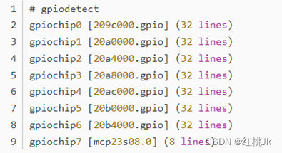
三列数据分别是 gpiochip 的名称(name)、标签(label)和行数(lines)。
2.3.2 gpioinfo
gpioinfo命令:
语法:gpioinfo [OPTIONS] <gpiochip> ...
选项:
-h, --help :查看帮助并退出
-v, --version :查看版本信息并退出
效果:
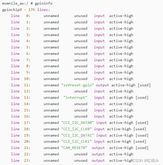
每个 line 所列出的四列数据分别表示 line 的名称(如果没有设定则显示 unnamed)、使用情况(如果未被使用则显示 unused)、方向(input 或者 output)和有效电平(active-low 或者 active-high)。
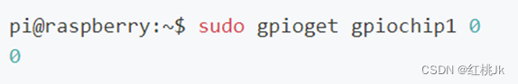
2.3.3 gpioset 、gpioget
gpioset或gpioget命令:例如,将gpiochip7组的第0个引脚电平设置为1
语法:gpioset或gpioget [OPTIONS] <chip name/number> <offset1>=<value1> <offset2>=<value2> ...
选项:
-l, --active-low :设置低电平为有效电平
-B, --bias=[as-is|disable|pull-down|pull-up] :设置 bias(默认使用 as-is)
-D, --drive=[push-pull|open-drain|open-source] :设置驱动模式(默认使用 push-pull)
-m, --mode=[exit|wait|time|signal] :设置完成后的动作模式
-s, --sec=SEC :当使用 --mode=time 选项时,指定等到的时间(单位:秒)
-u, --usec=USEC :当使用 --mode=time 选项时,指定等到的时间(单位:微秒)
-b, --background :设置完成后与控制终端分离
-h, --help :查看帮助并退出
-v, --version :查看版本信息并退出
效果示例:设置 gpiochip1 的 line 0 的值为 0(低电平)

效果示例:读取 gpiochip1 的 line 0 的值,返回值为0(即低电平)
2.3.3 gpio-event-mon
gpio-event-mon 命令可以检测端子变化状态
语法:gpio-event-mon [OPTIONS] <chip name/number> <offset 1> <offset 2> ...
选项:
-n <gpiochip>,监听对应的gpiochip信息,必须填写
-o <n>, 对应需要关注的chipline
-f, 监听下降沿信息
-r, 监听上升沿信息
-b <n>, 周期性监听chipline变化信息,单位为ms
-v, --version :查看版本信息并退出
效果示例:每100ms 监听gpiochip4-4 上升沿和下降沿状态,返回值为监听结果

2.4 gpiolib-debugfs
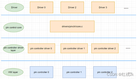
前面说过本质上使用gpio的核心是gpiolib,如果更详细的分类gpiolib的话,可以参照下图。
gpiolib-core:用于kernel driver调用(下文将提及)及上述2.2章节使用
gpiolib-sys:上文2.1章节使用
gpiolib-debugfs:用于debug相关信息
gpiolib-of:用于kernel driver中获取设备树DTS相关信息

因此通过gpiolib-debugfs在对应的用户空间可以获取到很多gpio相关信息
在用户空间的接口是/sys/kernel/debug/gpio和/sys/kernel/degbug/pinctrl
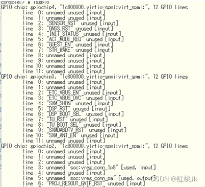
2.4.1 /sys/kernel/debug/gpio
对于该接口只有一个用法 即 cat /sys/kernel/debug/gpio
PS:如果系统中不包含/sys/kernel/debug/目录,可能需要使用mount -t debugfs nodev /sys/kernel/debug命令先挂载debugfs文件系统
不同平台,不同芯片厂商提供的gpiochip driver不同,导致输出结果有所差别
例如 telechips平台结果如下:

高通平台结果:

但基本遵循的逻辑是包含gpio-num,gpio-chip分组,gpio属性、电平状态等相关信息。
值得注意的是这里的信息是实时的,代表的是当前状态。通过前文提供的方法修改gpio状态后这里显示的信息也会变化
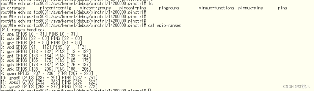
2.4.2/sys/kernel/debug/gpio/pinctrl
该目录是一个文件夹包含四个子目录

14200000.pinctrl 是一个文件夹,其中包含多个目录
![]()
每个目录都可以按照一定规则查看gpio信息,例如cat gpio-ranges结果如下:
在此可以看到更简洁的gpio组信息
其他目录会对gpio的信息描述更加清晰,但基本上是DTS中包含的端子不同状态下(例如普通状态,通信状态,STR sleep状态等)的全部属性信息。基本上不会随gpio状态当前的修改而产生变化,通过查看此文件,可以确认gpio理论上在某种状态下的应该配置的信息。
下面是 pinctrl-handles输出的内容
.

3 kernel空间使用gpio
在kernel中主要有两种配置方法,pinctrl方法、gpio方法。两种方法大同小异,原理是在kernel的driver代码中确认DTS中相关节点,再利用gpiolib提供的API函数,配置gpio。
两种方法其实对应的是linux中的pinctrl子系统和gpio子系统,下文中暂时不考虑两种子系统数据结构的组成,仅确认如何在驱动和DTS中使用两种子系统
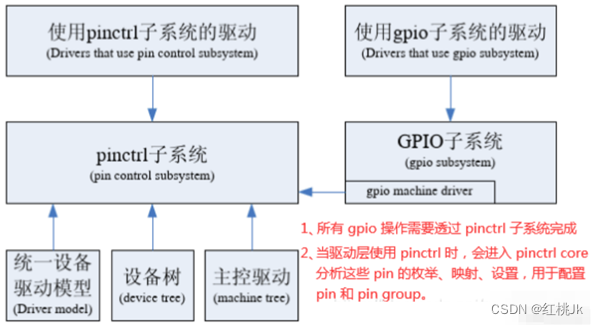
3.1 pinctrl子系统概念
许多SoC的内部都包含了pin控制器,通过pin控制器,我们可以匹配引脚的状态和功能特性。在了解pinctrl子系统之前,我们先来了解一些基本的概念。
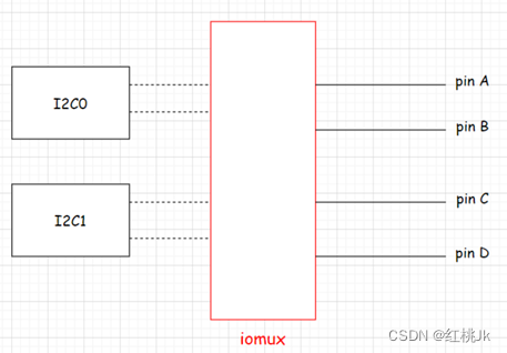
SoC的很多引脚都可以配置成不同的功能,如A1和A2两个引脚,既可以当作普通的gpio使用,又可以配置为i2c的SCL和SDA,也可以配置为其他功能等等,这称作引脚的复用(简称pinmux)。
除此之外,还可以配置引脚的电气属性,如上拉/下拉、输入/输出等,这称作引脚的配置(简称pinconf)。
有时需要将多个引脚组合在一起,以实现特定的功能,如spi接口、i2c接口等,需要以group为单位,访问、控制多个pin,这就是pin groups。引脚复用的功能,称作pin function。
一些SoC为了设计灵活,同一个功能,可以引出多个pin groups,如在芯片内部的i2c0的功能可能引出到pin groups {pinA, pinB},也可能引出到另外一个pin groups {pinC, pinD},但毫无疑问,这两个pin group不能同时active,毕竟芯片内部的i2c0的硬件逻辑只有一个,也就是说一个pin function可以对应多个pin groups。
pinctrl子系统,正是通过pin groups和pin function这两个概念,来管理SoC的引脚复用,pin function及pin groups一经确定,引脚的复用功能也就确认了
对于pinctrl而言,最底层是pin控制器,pin控制器驱动提供了引脚复用、配置的功能。pin control核心是一个硬件无关模块,提供了pin控制器驱动的注册、注销方法,从用户角度给出了操作pin的接口,这样,各个driver不需要关注pin控制器的底层硬件相关的内容。
因此,上层的driver调用pin control核心接口的主要需求有两个:
(1) 设置设备的引脚功能复用
(2) 设置设备的引脚电气特性
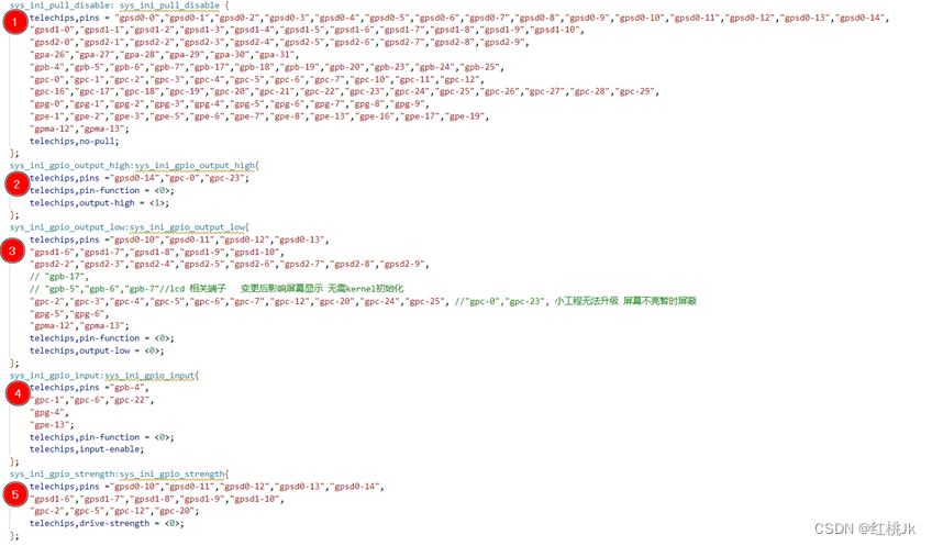
3.1.1 pinctrl 子系统 DTS设定
上面的需求在使用pinctrl时,更多的会强调组的概念。
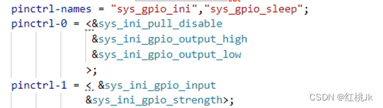
因此两个目标在设备树中对应的节点属性如下:
其中telechips,pins 为gpio标号,Pin-function 是引脚复用功能,output-high等描述为电器属性。
同时对这些gpio进行了分组,分为5组,可以理解为生成了5个pin控制器,这五组控制器将同一电气属性的pin进行了分组。(当然分组方式项目的需求,可以很灵活)
这5个pin控制器下,如下图可以结对为几种状态,进而统一管理。
例如:sys_gpio_ini对应pinctrl-0,sys_gpio_sleep对应pinctrl-1
(这里name的顺序和下方pinctrl-num的顺序是对应的。追加一个names同时需要追加一个num)
通过上述DTS完成了基本的pinctl控制器的设定。
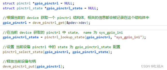
3.1.2 pinctrl 子系统 driver设定
在driver代码中使用Kernel提供的标准API即可完成对gpio的统一配置,针对上述DTS,相关代码如下:
相关API描述:
函数 |
函数原型 |
描述 |
devm_pinctrl_get 函数 |
struct pinctrl * devm_pinctrl_get(struct device *dev); |
函数功能:根据设备获取pin操作句柄,所有的pin操作必须基于此pinctrl句柄。与pinctrl_get接口功能完全一样,只是devm_pinctrl_get会将申请的pinctrl句柄做记账,绑定到设备句柄信息中。设备驱动申请pin资源,推荐优先使用devm_pinctrl_get接口。 返回值 pinctrl句柄 参数 dev:使用pin的设备,pinctrl子系统会通过设备名与pin配置信息匹配。 |
devm_pinctrl_put 函数 |
void devm_pinctrl_put(struct pinctrl *p); |
函数功能 释放pinctrl句柄,必须与devm_pinctrl_get配对使用。 返回值 无 参数 p:pinctrl句柄 |
pinctrl_lookup_state 函数 |
struct pinctrl_state * pinctrl_lookup_state(struct pinctrl *p, const char *name); |
函数功能 查找pin句柄指定状态下的状态句柄。 返回值 状态句柄 参数 p:pinctrl句柄 name:状态名称,A33平台上只有default一种状态 |
pinctrl_select_state函数 |
int pinctrl_select_state(struct pinctrl *p, struct pinctrl_state *s); |
函数功能 设置pin句柄的状态到硬件 返回值 0表示成功,其它表示失败 参数 p:pinctrl句柄 S:状态句柄 |
在 Linux 中,加 devm_ 开头的函数,代表这个函数支持资源管理。一般情况下,我们写一个驱动程序,在程序开头都会申请资源,比如内存、中断号等,万一后面哪一步申请出错,我们要回到第一步,去释放已经申请的资源,这样很麻烦。后来 Linux 开发出了很多 devm_ 开头的函数,代表这个函数有支持资源管理的版本,不管哪一步出错,只要错误退出,就会自动释放所申请的资源。虽然上面pinctl函数中也用到了devm_的函数,可以一定程度上避免资源申请未释放的问题,但在规范代码使用中,还是要进行规范的申请和释放。
3.2 gpio子系统
对于gpio子系统,一般使用时更普遍强调对单一端子的使用
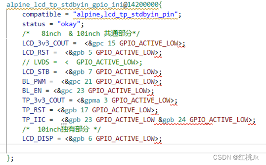
3.2.1 gpio子系统 DTS设定
下面的DTS描述gpio,是针对某个gpio进行逐个描述
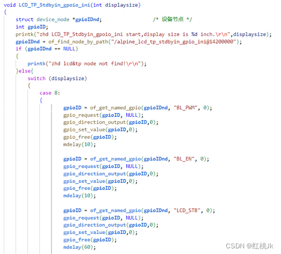
3.2.2 gpio子系统 driver设定
在drvier中的配置代码可以参照如下内容:
相关API描述:
函数 |
函数原型 |
描述 |
gpio_request函数 |
int gpio_request(unsigned gpio, const char *label) |
gpio_request函数用于申请一个GPIO管脚,在使用一个GPIO之前一定要使用gpio_request进行申请, gpio:要申请的gpio标号,使用of_get_named_gpio函数从设备树获取指定GPIO属性信息,此函数会返回这个GPIO的标号。 label:给gpio设置个名字。 返回值:0,申请成功;其他值,申请失败。 |
gpio_free函数 |
void gpio_free(unsigned gpio) |
如果不使用某个GPIO了,那么就可以调用gpio_free函数进行释放。 gpio:要释放的gpio标号。 返回值:无。 |
gpio_direction_input函数 |
int gpio_direction_input(unsigned gpio) |
此函数用于设置某个GPIO为输入, gpio:要设置为输入的GPIO标号。 返回值:0,设置成功;负值,设置失败。 |
gpio_direction_output函数 |
int gpio_direction_output(unsigned gpio, int value) |
此函数用于设置某个GPIO为输出,并且设置默认输出值, gpio:要设置为输出的GPIO标号。 value:GPIO默认输出值。 返回值:0,设置成功;负值,设置失败。 |
gpio_get_value函数 |
此函数用于获取某个GPIO的值(0或1),此函数是个宏,定义所示: #define gpio_get_value __gpio_get_value int __gpio_get_value(unsigned gpio) |
此函数用于获取某个GPIO的值(0或1) gpio:要获取的GPIO标号。 返回值:非负值,得到的GPIO值;负值,获取失败。 |
gpio_set_value函数 |
此函数用于设置某个GPIO的值,此函数是个宏,定义如下 #define gpio_set_value __gpio_set_value void __gpio_set_value(unsigned gpio, int value) |
此函数用于设置某个GPIO的值,此函数是个宏,定义如下 gpio:要设置的GPIO标号。 value:要设置的值。 返回值:无 关于gpio子系统常用的API函数就讲这些,这些是我们用的最多的。 |
另外在使用gpio函数前,首先要对找到设备树的节点,此时要用到相关of函数进行查找,下面举几个例子
函数 |
函数原型 |
描述 |
of_find_compatible_node 函数 |
struct device_node *of_find_compatible_node(struct device_node,*from, const char *type, const char *compatible) |
of_find_compatible_node 函数根据 device_type 和 compatible 这两个属性查找指定的节点 from:开始查找的节点,如果为 NULL 表示从根节点开始查找整个设备树。 type:要查找的节点对应的 type 字符串,也就是 device_type 属性值,可以为 NULL,表示忽略掉 device_type 属性。 compatible:要查找的节点所对应的 compatible 属性列表。 返回值:找到的节点,如果为 NULL 表示查找失败 |
of_get_named_gpio 函数 |
int of_get_named_gpio(struct device_node *np, const char *propname, int index) |
此函数获取 GPIO 编号,因为 Linux 内核中关于 GPIO 的 API 函数都要使用 GPIO 编号,此函数会将设备树中类似<&gpio5 7 GPIO_ACTIVE_LOW>的属性信息转换为对应的 GPIO 编号,此函数在驱动中使用很频繁! np:设备节点。 propname:包含要获取 GPIO 信息的属性名。 |
of_find_node_by_path |
static inline struct device_node *of_find_node_by_path(const char *path) |
of_find_node_by_path函数通过设备节点路径名获取设备节点 path参数:设备节点的路径名; 成功返回设备节点结构,失败时返回NULL; |
4 gpio IRQ相关简述
对于gpio中断要分为两部分理解,首先是linux 中断,其次是gpio中断。
4.1 linux中断描述及常用API
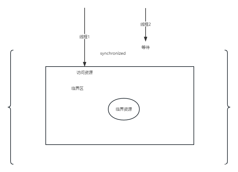
中断的本质,它其实是硬件产生了一个信号,然后告诉内核要去处理它。Linux处理中断很像用户空间(user space)处理信号(signal)一样,内核启动的时候注册了这个中断之后,当中断产生的时候(由硬件触发)就会调用对应的中断处理函数。这里需要注意在中断处理的时候要考虑公共资源的竞态和并发问题(这个本文不进行描述,需要考虑中断上下部,中断优先级等问题)
所以中断本身是一种资源,使用中断前必须先注册它,而且用完之后必须释放它。
因此关于中断的核心API也就能基本确认了
函数 |
函数原型 |
描述 |
request_irq函数 |
int request_irq(unsigned int irq, irq_handler_t handler, unsigned long flags, const char *name, void *dev) |
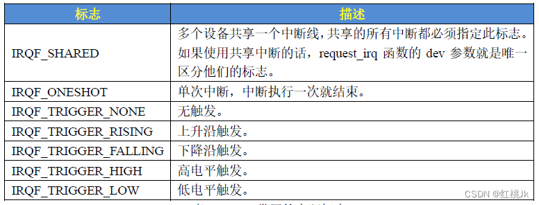
在 Linux内核中要想使用某个中断是需要申请的, request_irq函数用于申请中断, request_irq函数可能会导致睡眠,因此不能在中断上下文或者其他禁止睡眠的代码段中使用 request_irq函 数。 request_irq函数会激活 (使能 )中断,所以不需要我们手动去使能中断, 函数参数和返回值含义如下: irq:要申请中断的中断号。 handler:中断处理函数,当中断发生以后就会执行此中断处理函数。 flags:中断标志,可以在文件include/linux/interrupt.h里面查看所有的中断标志,里面查看所有的中断标志,这里我们介绍几个常用的中断标志,这些标志可以通过“|”来实现多种组合。
name:中断名字,设置以后可以在/proc/interrupts文件中看到对应的中断名字。 dev:如果将flags设置为IRQF_SHARED的话,dev用来区分不同的中断,一般情况下将dev设置为设备结构体,dev会传递给中断处理函数irq_handler_t的第二个参数。 返回值:0 中断申请成功,其他负值中断申请失败,如果返回-EBUSY的话表示中断已经被申请了。 |
free_irq函数 |
void free_irq(unsigned int irq, void *dev) |
使用中断的时候需要通过 request_irq函数申请,使用完成以后就要通过 free_irq函数释放 掉相应的中断。如果中断不是共享的,那么 free_irq会删除中断处理函数并且禁止中断。 irq:要释放的中断。 dev:如果中断设置为共享(IRQF_SHARED)的话,此参数用来区分具体的中断。共享中断只有在释放最后中断处理函数的时候才会被禁止掉。 |
中断处理函数 |
irqreturn_t (*irq_handler_t) (int, void *) |
使用 request_irq函数申请中断的时候需要设置中断处理函数,第一个参数是要中断处理函数要相应的中断号。第二个参数是一个指向 void的指针,也就是个通用指针,需要与 request_irq函数的 dev参数保持一致。用于区分共享中断的不同设备, dev也可以指向设备数据结构。中断处理函数的返回值为 irqreturn_t类型, irqreturn_t类型定义 如下所示:
IRQ_NONE 表示不是此设备产生的中断, IRQ_HANDLED 中断被正常处理, IRQ_WAKE_THREAD 唤醒中断处理线程,适用于常用 request_threaded_irq 注册的中断处理函数 |
中断使能与禁止函数 |
void enable_irq(unsigned int irq) void disable_irq(unsigned int irq) |
enable_irq和disable_irq用于使能和禁止指定的中断, irq:就是要禁止的中断号。 disable_irq函数要等到当前正在执行的中断处理函数执行完才返回,因此使用者需要保证不会产生新的中断,并且确保所有已经开始执行的中断处理程序已经全部退出。在这种情况下,可以使用另外 |

4.2 GPIO中断API
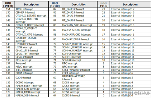
通过上述linux中断的核心API及概念,我们可以了解到,如果要使用一个中断最重要的一件事是确认它的中断号。那么gpio的中断号如何确认呢?
通常情况下,这个硬件中断号都会在芯片手册中提到。并详细描述不同功能对应的硬件中断号例如:
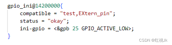
在linux通常情况下会通过DTS来描述硬件信息(通常情况下,DTS中对gpio的interrupt相关描述在厂商提供的源码中已经存在)例如:

此时我们则可以使用gpiolib中的函数gpio_to_irq()来查询gpio对应的中断号。gpio_to_irq()函数是在Linux内核中用于将GPIO(通用输入/输出)转换为中断请求(IRQ)线的函数。这个函数的主要作用是对于那些可以生成中断信号的GPIO引脚,获取到与这个GPIO引脚相关联的中断号。这样在编写驱动时,可以使用这个中断号来调用request_irq()函数,以便注册相关的中断处理函数。函数的原型为:int gpio_to_irq(unsigned int gpio);其中,gpio为待转换的GPIO编号,返回值为与该GPIO关联的中断号。
当GPIO引脚收到信号(譬如从高电平变为低电平)时,GPIO会向处理器发出中断请求,通知处理器进行相应的处理。gpio_to_irq()函数就是完成GPIO编号到中断号的映射工作。
请注意,并非所有的GPIO引脚都具备生成中断的能力,具体情况需要参考硬件手册或者SoC的数据手册。如果某个GPIO引脚不支持中断,那么gpio_to_irq()函数会返回一个负值,表示出错
函数 |
函数原型 |
描述 |
gpio_to_irq 函数 |
int gpio_to_irq(unsigned int gpio) |
gpio_to_irq函数来获取gpio对应的中断号,函数参数和返回值含义如下: gpio:要获取的GPIO编号。 返回值:GPIO对应的中断号。 |
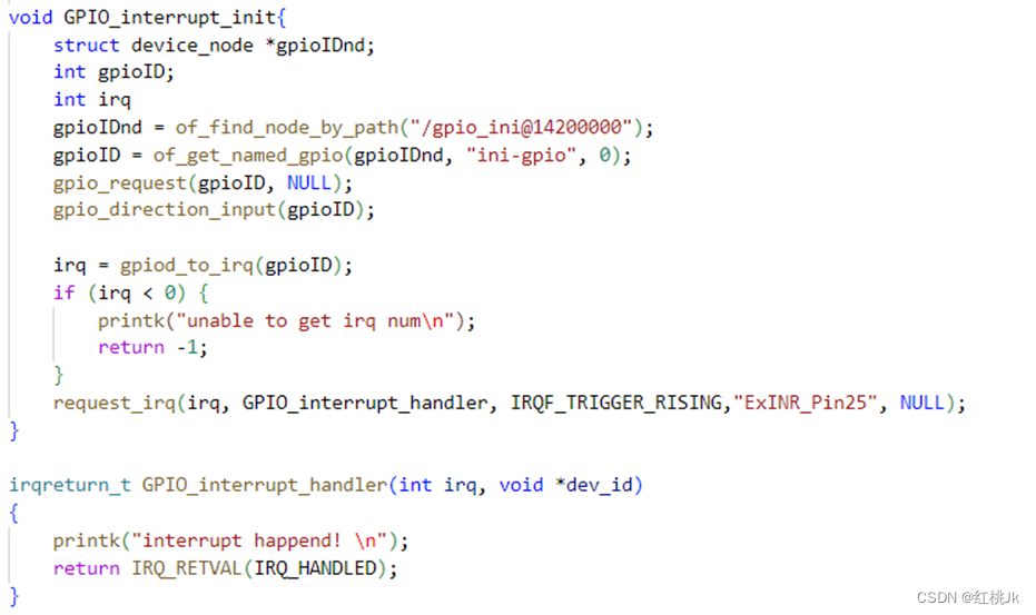
4.3 GPIO中断使用代码示例:
结合上述中API,即可完成申请中断的功能
设备树大致描述如下:
对应driver代码如下:
4.4 gpio中断效果确认
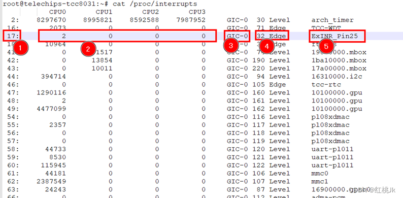
如果想要查看相关中断的一些状态或者使用情况,Linux在proc系统中提供了一个文件目录,通过命令 cat /proc/interrupts 可以查看
读取到的内容从左到右,分别为:1、逻辑(软件)中断号,2、中断在各CPU发生的次数,3、中断所属设备类名称,4、硬件中断号,5、注册中断处理函数的name。
参考:
Linux内核GPIO子系统分析_gpiod_get_value返回值-CSDN博客
Linux内核4.14版本——GPIO子系统(1)——gpiolib分析_gpiolib.h-CSDN博客
Linux内核的GPIO子系统驱动框架详解以及基于pinctrl和gpio子系统的LED驱动程序_gpio驱动代码流程-CSDN博客
Linux下控制GPIO的三种方法_linux gpio-CSDN博客
linux设备驱动程序——gpio控制_linux gpio驱动-CSDN博客
linux内核中的GPIO系统之(1):软件框架 (wowotech.net)
linux内核中的GPIO系统之(2):pin control subsystem (wowotech.net)
Linux内核中的GPIO系统之(3):pin controller driver代码分析 (wowotech.net)
linux内核中的GPIO系统之(4):pinctrl驱动的理解和总结 (wowotech.net)
linux内核中的GPIO系统之(5):gpio subsysem和pinctrl subsystem之间的耦合 (wowotech.net)
Linux下控制GPIO的三种方法_linux gpio控制-CSDN博客
pinctrl子系统分析(一)_soc pinmux-CSDN博客
RK3568平台开发系列讲解(Linux系统篇)pinctrl api介绍及实验-CSDN博客
linux驱动 — 常用API_linux驱动开发api函数-CSDN博客
Linux内核4.14版本——GPIO子系统(1)——gpiolib分析_linux gpio子系统-CSDN博客
Linux kernel GPIO user space interface - sergioprado.blog
GPIO 驱动程序接口 — Linux 内核文档 (kernel.org)
Linux内核GPIO子系统分析_int gpiod_get_value(const struct gpio_desc *desc)-CSDN博客