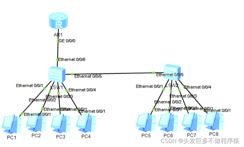
拓扑如下
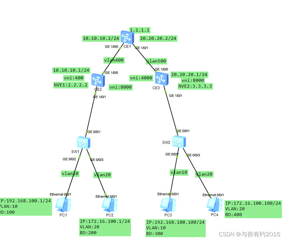
如上拓扑,PC1与PC3在同一个大二层广播域,PC2与PC4在同一个大二层广播域,我们要把PC1到PC3通过vxlan做通,PC2与PC4做通。
1.接入交换机SW1配置
vlan batch 10 20
interface GigabitEthernet0/0/1
port link-type trunk
port trunk allow-pass vlan 10 20
#
interface GigabitEthernet0/0/2
port link-type access
port default vlan 10
#
interface GigabitEthernet0/0/3
port link-type access
port default vlan 20
2.接入交换机2与SW1配置一样
vlan batch 10 20
interface GigabitEthernet0/0/1
port link-type trunk
port trunk allow-pass vlan 10 20
#
interface GigabitEthernet0/0/2
port link-type access
port default vlan 10
#
interface GigabitEthernet0/0/3
port link-type access
port default vlan 20
#
CE2配置
#
vlan batch 400 500
#
bridge-domain 100 //创建桥接域100 和200 ,桥接域本地生效
vxlan vni 4000 //创建vni (即vxlan 的id) 4000和8000,后面做隧道的时候要指定它
#
bridge-domain 200
vxlan vni 8000
interface Vlanif400 //创建vlan 400
ip address 10.10.10.1 255.255.255.0
#
interface MEth0/0/0
undo shutdown
#
interface GE1/0/0
undo shutdown
port link-type trunk
port trunk allow-pass vlan 400
#
interface GE1/0/1
undo shutdown
#
interface GE1/0/1.100 mode l2 在下联口上起了子接口,用于区分流量从哪个子接口上来,并
encapsulation dot1q vid 10 绑定到桥接域,其中的vid就是vlan id,本例中vlan10
bridge-domain 100
#
interface GE1/0/1.200 mode l2
encapsulation dot1q vid 20
bridge-domain 200
#
interface LoopBack0 起一个环回口,并为其配上IP
ip address 2.2.2.2 255.255.255.255
#
interface Nve1 创建vxlan隧道
source 2.2.2.2 指定源为本设备的环回地址
vni 4000 head-end peer-list 3.3.3.3 /为vni 4000做一条隧道,对端是3.3.3.3
vni 8000 head-end peer-list 3.3.3.3
#
interface NULL0
#
ospf 1 router-id 2.2.2.2 配置动态路由,便于隧道去学对端的路由
area 0.0.0.0
network 2.2.2.2 0.0.0.0 /宣告环回地址的路由
network 10.10.10.0 0.0.0.255 宣告vlan 400的路由
#
CE3的配置与CE2基本一样
#
bridge-domain 300
vxlan vni 4000
#
bridge-domain 400
vxlan vni 8000
#
aaa
interface Vlanif500
ip address 20.20.20.1 255.255.255.0
#
i
interface GE1/0/0
undo shutdown
port link-type trunk
port trunk allow-pass vlan 500
#
interface GE1/0/1
undo shutdown
#
interface GE1/0/1.1000 mode l2
encapsulation dot1q vid 10
bridge-domain 300
#
interface GE1/0/1.2000 mode l2
encapsulation dot1q vid 20
bridge-domain 400
#
interface LoopBack0
ip address 3.3.3.3 255.255.255.255
#
interface Nve1
source 3.3.3.3
vni 4000 head-end peer-list 2.2.2.2
vni 8000 head-end peer-list 2.2.2.2
#
interface NULL0
#
ospf 1 router-id 3.3.3.3
area 0.0.0.0
network 3.3.3.3 0.0.0.0
network 20.20.20.0 0.0.0.255
#
ssh authorization-type default aaa
#
ssh server cipher aes256_gcm aes128_gcm aes256_ctr aes192_ctr aes128_ctr aes256_
cbc aes128_cbc 3des_cbc
#
ssh server dh-exchange min-len 1024
#
ssh client cipher aes256_gcm aes128_gcm aes256_ctr aes192_ctr aes128_ctr aes256_
cbc aes128_cbc 3des_cbc
#
user-interface con 0
#
vm-manager
#
return
CE1基本没什么配置,起两个vlan,并为到CE2和CE3的接口做trunk,开启ospf
#
vlan batch 400 500
#
interface Vlanif400
ip address 10.10.10.2 255.255.255.0
#
interface Vlanif500
ip address 20.20.20.2 255.255.255.0
#
interface MEth0/0/0
undo shutdown
#
interface GE1/0/0
undo shutdown
port link-type trunk
port trunk allow-pass vlan 400 500
#
interface GE1/0/1
undo shutdown
port link-type trunk
port trunk allow-pass vlan 400 500
#
interface LoopBack0
ip address 1.1.1.1 255.255.255.255
#
interface NULL0
#
ospf 1 router-id 1.1.1.1
area 0.0.0.0
network 1.1.1.1 0.0.0.0
network 10.10.10.0 0.0.0.255
network 20.20.20.0 0.0.0.255
#
好了,配置完成
查看邻居

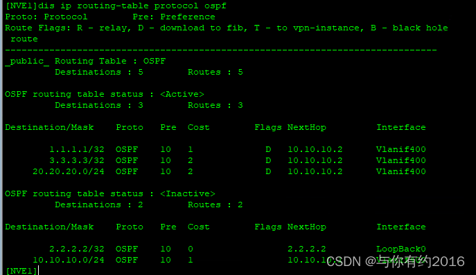
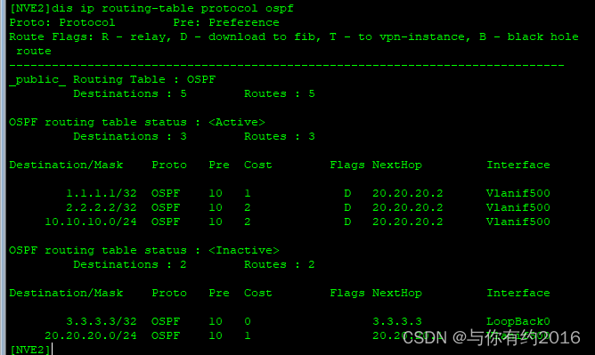
查看路由表
ping 测试,PC1 到 PC3

PC4到PC2

最后看一下抓包,我们先在CE2的上行口上抓从PC4到PC2过的报文,这是收到解封装前的报文

再看回去的报文,也差不多

我们最后再看一下在下行口上抓到的解封装后的报文是什么样的

如果有解释不正确的地方,请大神多多指正,感谢


![[BJDCTF2020]BJD hamburger competition-buuctf](https://img-blog.csdnimg.cn/direct/34c9a13bc53243ce90a87348b5572408.png)