Overview
AG32 device provide a independent watchdog, which connects to the Advanced Peripheral Bus(APB)。
The independent watchdog is based on a 12-bit downcounter and 8-bit prescaler. It is clocked from an independent 32 kHz internal RC and as it operates independently from the main clock, it can operate in Stop and Standby modes. It can be used either as a watchdog to reset the device when a problem occurs, or as a free-running timer for application timeout management. It is hardware- or software-configurable through the option bytes.
The Watchdog module is an AMBA slave module and connects to the Advanced Peripheral Bus (APB).
The Watchdog module consists of a 32-bit down counter with a programmable timeout interval that has the capability to generate an interrupt and a reset signal on timing out. It is intended to be used to apply a reset to a system in the event of a software failure.
Independent watchdog (IWDG)
IWDG main features
(1) Free-running down-counter
(2) clocked from an LSI oscillator when Stop and normal modes and from LSE when Standby mode)
(3) Reset (if watchdog activated) when the down-counter value of 0x000 is reached
IWDG functional description
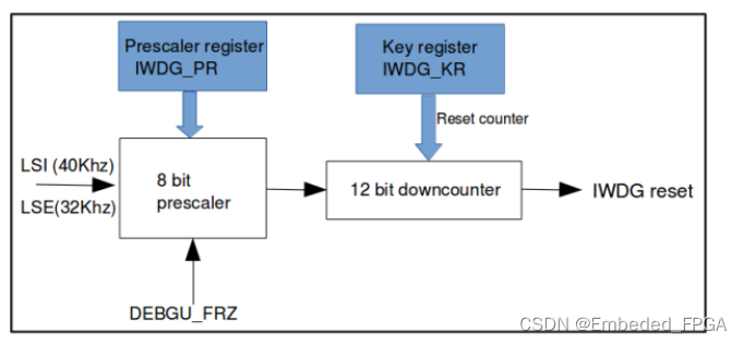
Figure below shows the functional blocks of the independent watchdog module.
When the independent watchdog is started, the counter starts counting down from the reset value of 0xFFF. When it reaches the end of count value (0x000) a reset signal is generated (IWDG reset).
Whenever the key value 1010 is written in the IWDG_KR register, the down-counter is initialized and the watchdog reset is prevented.
Watchdog clock
If the Independent watchdog (IWDG) is started by either hardware option or software access,
(1) Under run or stop mode
Select LSE or LSI clock source by setting the IWDG_STOP_CLKSEL bit in the Backup domain control register(RCC_BDCR).
(2) Under Standby mode
HW will select LSE as clock source for IWDG.
Debug mode
When the mcu enter debug mode, the IWDG counter either continues to work normally or stop, depending on DBG_IWDG_STOP configuration bit in DBG module.
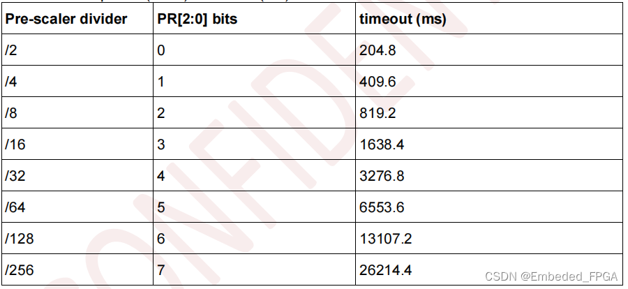
IWDG timeout period (in ms) at 40 kHz (LSI)
Features
The features of the Watchdog module are:
• 32-bit down counter with a programmable timeout interval.
• Separate Watchdog clock with clock enable for flexible control of the timeout interval.
• Interrupt output generation on timeout.
• Reset signal generation on timeout if the interrupt from the previous timeout remains unserviced by
software.
• Lock register to protect registers from being altered by runaway software.
• Identification registers that uniquely identify the Watchdog module. These can be used by software to
automatically configure itself
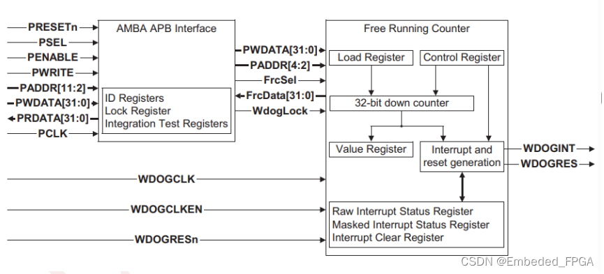
Figure below shows a simplified block diagram of the Watchdog module.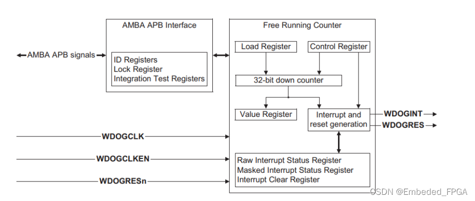
Programmable parameters
The following Watchdog module parameters are programmable:
• interrupt generation enable/disable
• interrupt masking
• reset signal generation enable and/disable
• interrupt interval.
Watchdog module overview
The Watchdog module is based around a 32-bit down counter that is initialized from the Reload Register, WdogLoad. The counter decrements by one on each positive clock edge of WDOGCLK whenthe clock enable WDOGCLKEN is HIGH. When the counter reaches zero, an interrupt is generated. On the next enabled WDOGCLK clock edge the counter is reloaded from the WdogLoad Register and the count down sequence continues. If the interrupt is not cleared by the time that the counter next reaches zero then the Watchdog module asserts the reset signal, WDOGRES, and the counter is stopped.
WDOGCLK can be equal to or be a sub-multiple of the PCLK frequency. However, the positive edges of WDOGCLK and PCLK must be synchronous and balanced.
The Watchdog module interrupt and reset generation can be enabled or disabled as required by use of the Control Register, WdogControl. When the interrupt generation is disabled then the counter is stopped. When the interrupt is re-enabled then the counter starts from the value programmed in WdogLoad, and not from the last count value.
Write access to the registers in the Watchdog module can be disabled by the use of the Watchdog module Lock Register, WdogLock. Writing a value of 0x1ACCE551 to the register enables write accesses to all of the other registers. Writing any other value disables write accesses to all registers except the Lock Register. This feature protects the Watchdog module registers from being spuriously changed by runaway software that might otherwise disable the Watchdog module operation.
Functional description
The Watchdog module block diagram is shown in Figure below.
AMBA APB interface
The AMBA APB slave interface generates read and write decodes for accesses to all registers in the Watchdog module. The Lock Register, WdogLock, is used to control the enabling of write accesses to all the other registers in order to ensure software cannot unintentionally disable the Watchdog module operation.
Free running counter block
The free running counter block contains the 32-bit down counter functionality and generates the interrupt and reset signal outputs. The counter and interrupt/reset logic is clocked independently of
PCLK by WDOGCLK in conjunction with a clock enable, WDOGCLKEN, although there are constraints on the relationship between PCLK and WDOGCLK. See Clock signals for details of these constraints.
Interface resets
The Watchdog module is reset by:
• the global reset signal, PRESETn
• a block specific reset signal, WDOGRESn.
PRESETn can be asserted asynchronously to PCLK but must be deasserted synchronously to the rising edge of PCLK. PRESETn is used to reset the state of the Watchdog module registers. The Watchdog module requires PRESETn to be asserted LOW for at least one period of PCLK. The values of the registers after reset are defined in Chapter 3 Programmer’s Model.
WDOGRESn can be asserted asynchronously to WDOGCLK but must be deasserted synchronously to
the rising edge of WDOGCLK. WDOGRESn is used to reset the state of registers in the WDOGCLK domain. The Watchdog module requires WDOGRESn to be asserted LOW for at least one period of WDOGCLK.
Clock signals
The Watchdog uses two input clocks:
PCLK This is used to time all APB accesses to the Watchdog module registers.
WDOGCLK
This clock, in conjunction with its clock enable, WDOGCLKEN, is used to clock the Watchdog module counter and its associated interrupt and reset generation logic. The Watchdog counter only decrements
on a rising edge of WDOGCLK when WDOGCLKEN is HIGH. The relationship between WDOGCLK
and PCLK must observe the following constraints:
• the rising edges of WDOGCLK must be synchronous and balanced with a rising edge of PCLK
• the WDOGCLK frequency cannot be greater than the PCLK frequency.
Operation
After the initial application and release of PRESETn and WDOGRESn, the Control Register is reset and interrupt and reset generation is disabled. The Lock Register, WdogLock, is initialized in the unlocked state so that write access to all Watchdog module registers is enabled. The Watchdog counter remains at its initial value (0xFFFFFFFF) until the interrupt generation is enabled by setting the INTEN bit in the WdogControl Register.
The WdogLoad Register must be programmed with the desired timeout interval before the Watchdog module is enabled. After the INTEN bit is set, the counter is loaded with the value in the WdogLoad
Register on the next rising edge of WDOGCLK enabled by WDOGCLKEN. On each subsequent
enabled WDOGCLK rising edge the counter decrements by one. When the counter reaches zero an interrupt is generated and the Watchdog interrupt signal, WDOGINT, is asserted. The counter is then
reloaded from the value in the WdogLoad Register and starts another count down sequence.
The interrupt is cleared by a write of any data value to the WdogIntClr Register. This causes the counter to reload with the value held in the WdogLoad Register and another count down sequence starts. If the interrupt is not cleared before the counter next reaches zero then the WDOGRES signal is asserted if the reset enable bit, RESEN, in the WdogControl Register is set. After the WDOGRES
signal is asserted, the counter stops.
In a SoC, the WDOGRES signal is used to reset a system that has got into an unpredictable state.
Therefore, the Watchdog module expects to be reset by PRESETn and WDOGRESn and the initialization procedure starts again.
To protect the Watchdog module registers from being changed unintentionally, the Lock Register,
WdogLock, must be used to disable the write access to the Watchdog module registers after registers have been modified. To enable write access to all registers, write 0x1ACCE551 to the Lock Register,
WdogLock. After writing to the required Watchdog registers, disable write access to all registers except the Lock Register by writing any value other than 0x1ACCE551 to the Lock Register. Reading the Lock
Register returns the lock status rather than the 32-bit value written. Therefore, when write accesses are disabled, reading the lock register returns 0x00000001 (locked) otherwise the return value is
0x00000000 (unlocked).
If the Load Register, WdogLoad, is written to with a new value while the Watchdog counter is decrementing then the counter is reloaded immediately with the new load value and continues
decrementing from the new value. Writing to WdogLoad does not clear an active interrupt. An interrupt must be specifically cleared by writing to the Interrupt Clear Register, WdogIntClr.
If the interrupt generation is disabled by clearing the INTEN bit in the Control Register, WdogControl, the counter stops at its current value. When the interrupt generation is enabled again the counter reloads from the Load Register, WdogLoad, and starts to decrement.


![Docker | 将自己的docker镜像推送到docker hub[图文详情]](https://img-blog.csdnimg.cn/direct/0d67ea25c41b475abc2e199a671ad5d2.png)