前言
一、概念
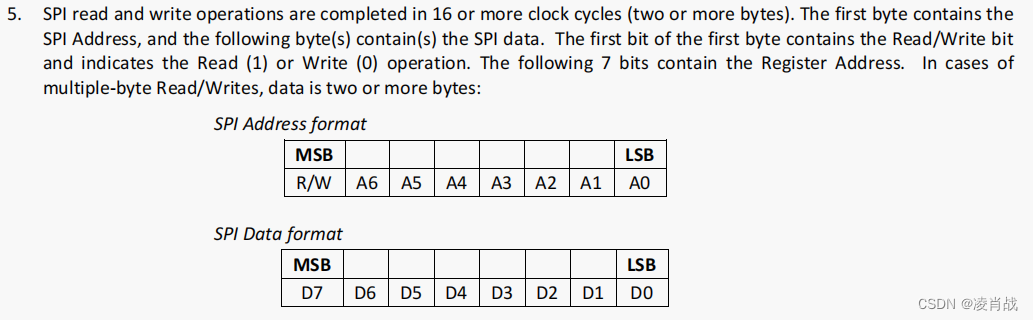
SPI(Serial Peripheral Interface一一串行外设接口)总线是Motorola公司 [2]推出的一种同步串行接口技术。SPI总线系统是一种同步串行外接口,允许MCU/MPU与各种外围设备以串行方式进行通信,数据交换。外围设备包括FLASHRAM、A/D转换器、网络控制器、MCU等。SPI是一种高速的,全双工,同步的通信总线。(来自百度百科)
关键词: 串行 高速 全双工(发送的同时可以接收)
二、硬件特性
1、线制说明
三线制:CLK时钟、 CS片选、 MOSI(此线作为输入输出线),三线是SPI的半双工通信,单根数据线可以分时发送和接收;
四线制: CLK时钟、 CS片选、 MOSI(主机输出)、MISO(主机输入),标准四线是全双工
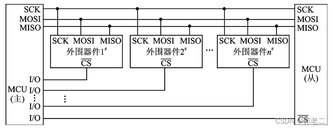
2、电气连接
标准四线
三线
3、极性/模式
spi根据极性和相位有四种模式
三、驱动软件
此说明以linux内核5.10.165, Designware SPI core controller 外设IP核为例总结
1、主要文件和作用
spi-dw-mmio.c
spi外设控制器设备树节点解析,将spi外设封装成platform设备,对platform设备设备的操作封装;
以platform的device成员,创建struct dw_spi_mmio 后,对struct dw_spi_mmio成员初始化;
解析设备树中外设寄存器 时钟等资源赋值给其中struct dw_spi dws 成员的子成员,struct dw_spi结构定义于spi-dw.h
此文件主要结构:
struct dw_spi_mmio {
	struct dw_spi  dws;
	struct clk     *clk;
	struct clk     *pclk;
	void           *priv;
	struct reset_control *rstc;
};
spi-dw-core.c
对struct dw_spi 结构的操作封装,spi外设中断处理函数的处理,对struct dw_spi的成员struct spi_controller *master的初始化
此文件主要结构:
struct dw_spi {
	struct spi_controller	*master;  //对spi外设封装表示

	void __iomem		*regs;  //spi外设的寄存器地址
	unsigned long		paddr;
	int			irq;
	u32			fifo_len;	/* depth of the FIFO buffer */
	u32			max_mem_freq;	/* max mem-ops bus freq */
	u32			max_freq;	/* max bus freq supported */

	u32			caps;		/* DW SPI capabilities */

	u32			reg_io_width;	/* DR I/O width in bytes */
	u16			bus_num;
	u16			num_cs;		/* supported slave numbers */
	void (*set_cs)(struct spi_device *spi, bool enable);

	/* Current message transfer state info */
	void			*tx;
	unsigned int		tx_len;
	void			*rx;
	unsigned int		rx_len;
	u8			buf[SPI_BUF_SIZE];
	int			dma_mapped;
	u8			n_bytes;	/* current is a 1/2 bytes op */
	irqreturn_t		(*transfer_handler)(struct dw_spi *dws);
	u32			current_freq;	/* frequency in hz */
	u32			cur_rx_sample_dly;
	u32			def_rx_sample_dly_ns;

	/* Custom memory operations */
	struct spi_controller_mem_ops mem_ops;

	/* DMA info */
	struct dma_chan		*txchan;
	u32			txburst;
	struct dma_chan		*rxchan;
	u32			rxburst;
	u32			dma_sg_burst;
	unsigned long		dma_chan_busy;
	dma_addr_t		dma_addr; /* phy address of the Data register */
	const struct dw_spi_dma_ops *dma_ops;
	struct completion	dma_completion;

#ifdef CONFIG_DEBUG_FS
	struct dentry *debugfs;
	struct debugfs_regset32 regset;
#endif
};
spidev.c
对挂载spi外设上的spi设备进行读写访问的通用驱动接口封装, 在此对于spi设备的操作也是通用的字符设备操作结构体,如下
static const struct file_operations spidev_fops = {
	.owner =	THIS_MODULE,
	/* REVISIT switch to aio primitives, so that userspace
	 * gets more complete API coverage.  It'll simplify things
	 * too, except for the locking.
	 */
	.write =	spidev_write,
	.read =		spidev_read,
	.unlocked_ioctl = spidev_ioctl,
	.compat_ioctl = spidev_compat_ioctl,
	.open =		spidev_open,
	.release =	spidev_release,
	.llseek =	no_llseek,
};
spi.c
spi驱动的核心层;
对于spi外设到spi设备信息读写接口;
spi外设控制器的最终注册;
spi消息队列的管理;
spi_controller和spi_device的分配接口;
2、主要数据结构
spi外设的表示:
struct spi_controller {
	struct device	dev;

	struct list_head list; //一个芯片不只有一个spi外设,对于一个spi外设会将此外设挂到spi外设的列表里

	/* other than negative (== assign one dynamically), bus_num is fully
	 * board-specific.  usually that simplifies to being SOC-specific.
	 * example:  one SOC has three SPI controllers, numbered 0..2,
	 * and one board's schematics might show it using SPI-2.  software
	 * would normally use bus_num=2 for that controller.
	 */
	s16			bus_num;

	/* chipselects will be integral to many controllers; some others
	 * might use board-specific GPIOs.
	 */
	u16			num_chipselect;
	//一些钩子函数的定义//

};
spi设备的表示:
struct spi_device {
	struct device		dev;
	struct spi_controller	*controller;
	struct spi_controller	*master;	/* compatibility layer */
	u32			max_speed_hz;
	u8			chip_select;
	u8			bits_per_word;
	bool			rt;
	u32			mode;
#define	SPI_CPHA	0x01			/* clock phase */
#define	SPI_CPOL	0x02			/* clock polarity */
#define	SPI_MODE_0	(0|0)			/* (original MicroWire) */
#define	SPI_MODE_1	(0|SPI_CPHA)
#define	SPI_MODE_2	(SPI_CPOL|0)
#define	SPI_MODE_3	(SPI_CPOL|SPI_CPHA)
#define	SPI_CS_HIGH	0x04			/* chipselect active high? */
#define	SPI_LSB_FIRST	0x08			/* per-word bits-on-wire */
#define	SPI_3WIRE	0x10			/* SI/SO signals shared */
#define	SPI_LOOP	0x20			/* loopback mode */
#define	SPI_NO_CS	0x40			/* 1 dev/bus, no chipselect */
#define	SPI_READY	0x80			/* slave pulls low to pause */
#define	SPI_TX_DUAL	0x100			/* transmit with 2 wires */
#define	SPI_TX_QUAD	0x200			/* transmit with 4 wires */
#define	SPI_RX_DUAL	0x400			/* receive with 2 wires */
#define	SPI_RX_QUAD	0x800			/* receive with 4 wires */
#define	SPI_CS_WORD	0x1000			/* toggle cs after each word */
#define	SPI_TX_OCTAL	0x2000			/* transmit with 8 wires */
#define	SPI_RX_OCTAL	0x4000			/* receive with 8 wires */
#define	SPI_3WIRE_HIZ	0x8000			/* high impedance turnaround */
	int			irq;
	void			*controller_state;
	void			*controller_data;
	char			modalias[SPI_NAME_SIZE];
	const char		*driver_override;
	int			cs_gpio;	/* LEGACY: chip select gpio */
	struct gpio_desc	*cs_gpiod;	/* chip select gpio desc */
	struct spi_delay	word_delay; /* inter-word delay */

	/* the statistics */
	struct spi_statistics	statistics;

	/*
	 * likely need more hooks for more protocol options affecting how
	 * the controller talks to each chip, like:
	 *  - memory packing (12 bit samples into low bits, others zeroed)
	 *  - priority
	 *  - chipselect delays
	 *  - ...
	 */
};
spi消息的表示:
struct spi_message {
	struct list_head	transfers;

	struct spi_device	*spi;

	unsigned		is_dma_mapped:1;

	/* REVISIT:  we might want a flag affecting the behavior of the
	 * last transfer ... allowing things like "read 16 bit length L"
	 * immediately followed by "read L bytes".  Basically imposing
	 * a specific message scheduling algorithm.
	 *
	 * Some controller drivers (message-at-a-time queue processing)
	 * could provide that as their default scheduling algorithm.  But
	 * others (with multi-message pipelines) could need a flag to
	 * tell them about such special cases.
	 */

	/* completion is reported through a callback */
	void			(*complete)(void *context);
	void			*context;
	unsigned		frame_length;
	unsigned		actual_length;
	int			status;

	/* for optional use by whatever driver currently owns the
	 * spi_message ...  between calls to spi_async and then later
	 * complete(), that's the spi_controller controller driver.
	 */
	struct list_head	queue;
	void			*state;

	/* list of spi_res reources when the spi message is processed */
	struct list_head        resources;
};
3、驱动初始化流程
3.1、spi外设初始化流程

3.2、下挂设备初始化流程

四、应用层
1、消息结构 struct spi_ioc_transfer
struct spi_ioc_transfer {
	__u64		tx_buf;
	__u64		rx_buf;

	__u32		len;
	__u32		speed_hz;

	__u16		delay_usecs;
	__u8		bits_per_word;
	__u8		cs_change;
	__u8		tx_nbits;
	__u8		rx_nbits;
	__u8		word_delay_usecs;
	__u8		pad;

	/* If the contents of 'struct spi_ioc_transfer' ever change
	 * incompatibly, then the ioctl number (currently 0) must change;
	 * ioctls with constant size fields get a bit more in the way of
	 * error checking than ones (like this) where that field varies.
	 *
	 * NOTE: struct layout is the same in 64bit and 32bit userspace.
	 */
};
2、应用编程示例
打开设备描述符:
spi_fd = open(devname, O_RDWR); devname为/dev/spidev*.* ,表示第几个spi外设下的第几个设备,如/dev/spidev0.0;
初始化配置读写模式、最大速率、传输字位数:
 ioctl(spi_fd, SPI_IOC_WR_MODE, mode); //mode  为 0  1  2  3 具体看控制的外部器件支持哪种模式
 ioctl(spi_fd, SPI_IOC_RD_MODE, mode);
 ioctl(spi_fd, SPI_IOC_WR_BITS_PER_WORD, bits);  //bits  可以为 8
 ioctl(spi_fd, SPI_IOC_RD_BITS_PER_WORD, bits);
 ioctl(spi_fd, SPI_IOC_WR_MAX_SPEED_HZ, speed);  //被控制器件支持的最大速率
 ioctl(spi_fd, SPI_IOC_RD_MAX_SPEED_HZ, speed);
读外部器件数据
struct spi_ioc_transfer transfer;
uint8_t spidev_read(uint8_t addr)
{
        unit8_t  out[3]={0},in[3]={0};
        out[0] = rd_cmd; //不同的芯片定义不同,看芯片手册具体描述
        out[1] = addr;   //不同的芯片定义不同
        out[2] = dummy_data; //这里是0x00

        transfer.tx_buf = (unsigned long)out;
        transfer.rx_buf = (unsigned long)in;
        transfer.len = 3;
        int ret = ioctl(spi_file, SPI_IOC_MESSAGE(1), &transfer);
        if (ret >= 3)
        {

            return in[2];
        }
        else
        {
            return  0xff;  //error
        }
}
向外部器件写数据
void spidev_write(uint8_t addr, uint8_t data)
{
        unit8_t  out[3]={0};
        out[0] = wr_cmd; //不同的芯片定义不同
        out[1] = addr;   //不同的芯片定义不同
        out[2] = data;
        transfer.tx_buf = (unsigned long)out;
        transfer.len = 3;
        int ret = ioctl(spi_file, SPI_IOC_MESSAGE(1), &transfer);
        if (ret >= 3)
        {
           // success
        }
        else
        {
           //error
        }
}