目录

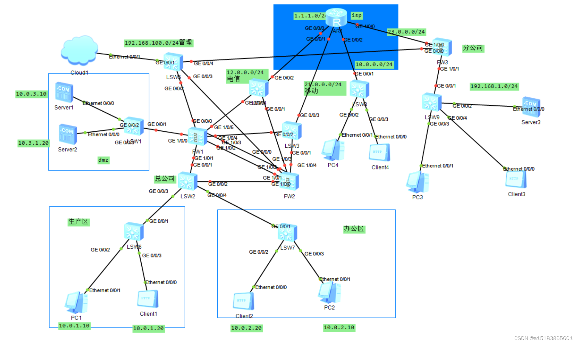
实验要求
接防火墙综合实验一!
7,办公区设备可以通过电信链路和移动链路上网(多对多的NAT,并且需要保留一个公网IP不能用来转换)。
8,分公司设备可以通过总公司的移动链路和电信链路访问到Dmz区的http服务器。
9,多出口环境基于带宽比例进行选路,但是,办公区中10.0.2.10该设备只能通过电信的链路访问互联网。链路开启过载保护,保护阈值80%。
10,分公司内部的客户端可以通过域名访问到内部的服务器,公网设备也可以通过域名访问到分公司内部服务器。
11,游客区仅能通过移动链路访问互联网。
IP地址配置
办公区新设备:
client5:

公网:
ISP:
[ISP]dis ip int b
*down: administratively down
^down: standby
(l): loopback
(s): spoofing
The number of interface that is UP in Physical is 6
The number of interface that is DOWN in Physical is 1
The number of interface that is UP in Protocol is 4
The number of interface that is DOWN in Protocol is 3

Interface                         IP Address/Mask      Physical   Protocol
GigabitEthernet0/0/0              12.0.0.1/24          up         up
GigabitEthernet0/0/1              21.0.0.1/24          up         up
GigabitEthernet0/0/2              unassigned           up         down
GigabitEthernet3/0/0              unassigned           up         down
GigabitEthernet4/0/0              unassigned           down       down
LoopBack0                         1.1.1.1/24           up         up(s)
NULL0                             unassigned           up         up(s)
[ISP]int g3/0/0
[ISP-GigabitEthernet3/0/0]ip add 100.0.0.1 24
[ISP-GigabitEthernet3/0/0]int g0/0/2
[ISP-GigabitEthernet0/0/2]ip add 23.0.0.1 24
Jul 12 2024 17:19:45-08:00 ISP %%01IFNET/4/LINK_STATE(l)[0]:The line protocol IP
 on the interface GigabitEthernet0/0/2 has entered the UP state.
[ISP-GigabitEthernet0/0/2]dis ip int b
*down: administratively down
^down: standby
(l): loopback
(s): spoofing
The number of interface that is UP in Physical is 6
The number of interface that is DOWN in Physical is 1
The number of interface that is UP in Protocol is 6
The number of interface that is DOWN in Protocol is 1

Interface                         IP Address/Mask      Physical   Protocol
GigabitEthernet0/0/0              12.0.0.1/24          up         up
GigabitEthernet0/0/1              21.0.0.1/24          up         up
GigabitEthernet0/0/2              23.0.0.1/24          up         up
GigabitEthernet3/0/0              100.0.0.1/24         up         up
GigabitEthernet4/0/0              unassigned           down       down
LoopBack0                         1.1.1.1/24           up         up(s)
NULL0                             unassigned           up         up(s)
[ISP-GigabitEthernet0/0/2]
server5:
client3:
PC6:
分公司:
server4:
client4:
PC3:
防火墙:
为了区分防火墙,改一下名字:
FW1:
[USG6000V1]sysname FW1FW2:
<USG6000V1>sys
[USG6000V1]sysname FW2
[FW2]int g0/0/0
[FW2-GigabitEthernet0/0/0]ip add 192.168.10.2 24
[FW2-GigabitEthernet0/0/0]dis ip int b
2024-07-12 09:09:31.300
*down: administratively down
^down: standby
(l): loopback
(s): spoofing
(d): Dampening Suppressed
(E): E-Trunk down
The number of interface that is UP in Physical is 5
The number of interface that is DOWN in Physical is 5
The number of interface that is UP in Protocol is 3
The number of interface that is DOWN in Protocol is 7

Interface                         IP Address/Mask      Physical   Protocol
GigabitEthernet0/0/0              192.168.10.2/24      up         up
GigabitEthernet1/0/0              unassigned           up         down
GigabitEthernet1/0/1              unassigned           up         down
GigabitEthernet1/0/2              unassigned           down       down
GigabitEthernet1/0/3              unassigned           down       down
GigabitEthernet1/0/4              unassigned           down       down
GigabitEthernet1/0/5              unassigned           down       down
GigabitEthernet1/0/6              unassigned           down       down
NULL0                             unassigned           up         up(s)
Virtual-if0                       unassigned           up         up(s)
[FW2-GigabitEthernet0/0/0]service-manage all permit
接下来便可以通过Web界面控制了。


配置完成。
需求七
办公区设备可以通过电信链路和移动链路上网(多对多的NAT,并且需要保留一个公网IP不能用来转换)。
新建电信区:
新建移动区: 将对应接口划归到各自区域:

 新建安全策略放通办公区到电信或移动的流量:

新建源地址池(保留一个IP地址):
电信:
移动: 
多对多NAT:

 测试:
测试:
PC2ping1.1.1.1:

查看 server-map表:

走的电信。
client2ping1.1.1.1:

查看 server-map表:

走的移动。
使用非办公区设备访问1.1.1.1:
不通!

至此需求完成。
需求八
分公司设备可以通过总公司的移动链路和电信链路访问到Dmz区的http服务器。
在FW1中新建目的地址池(server1设为httpserver):
FW1中新建目标NAT: 原始数据包中的目的地址是公网进入私网时需要在哪台设备上作地址转换。
这里需要建一条安全策略放通转换后的流量:

测试:

这样外网便能访问到DMZ区的httpserver。
在FW2上配置源地址NAT:
新建源地址池:
新建源NAT(同时新建安全策略):

 测试:
测试:


现在测试是否能用分公司client3访问总公司DMZhttpserver:
至此需求完成。
需求九
多出口环境基于带宽比例进行选路,但是,办公区中10.0.2.10该设备只能通过电信的链路访问互联网。链路开启过载保护,保护阈值80%。
基于带宽比例进行选路:
新建链路接口(勾选源进源出,可以保证不浪费链路资源):
电信:
移动:
修改全局选路策略(开启源IP会话保持,可以防止过载后链路断开而导致的服务强制结束):
链路开启过载保护(修改接口中):
移动:
电信:
查看:
办公区中10.0.2.10该设备只能通过电信的链路访问互联网:
做策略路由:

至此配置完成。
需求十
分公司内部的客户端可以通过域名访问到内部的服务器,公网设备也可以通过域名访问到分公司内部服务器。
分公司内部的server4作为httpserver,设定域名为www.openlab.com 
作目标NAT:
新建地址池:
新建目标NAT(一起建立新的安全策略):

将公网内的server5作为DNS服务器并添加HTTP服务器的信息:
在其他有需求的客户端上配置DNS服务器:
client3:
client4:
公网访问测试:
成功。
私网访问需要作双向NAT(因为同属于一个trust区域,故不用作安全策略):

 测试:
测试:
client4成功通过域名访问到了HTTP server!

至此需求完成。
需求十一
游客区仅能通过移动链路访问互联网。
作源NAT(顺便放通游客区发往公网的流量):


作策略路由:


测试:
关闭移动链路:![]()
使用PC4访问外网:
失败!
开启移动链路:![]()
重试:
成功!
查看server-map表:

走的移动。
至此配置完成。