目录
解决非骨干区域没有和骨干区域直接相连
进程互引
进程概念
- 利用OPSF多进程原理解决,非骨干区域没有和骨干区域直接相连的问题
- OSPF可以运行多个进程,每一个进程是独立运行的,进程之间的路由不能互相学习,不同进程类似不同的协议,如果要学习不同进程中的路由,需要做进程的引入
原理
同一台路由器的两个OSPF进程不能互相学习路由,不同路由器的不同OSPF进程之间不影响邻居的建立,以及路由学习情况,通过进程互相引入的方式,学习不同进程下的路由,就像在OSPF中引入其他路由协议一样
配置
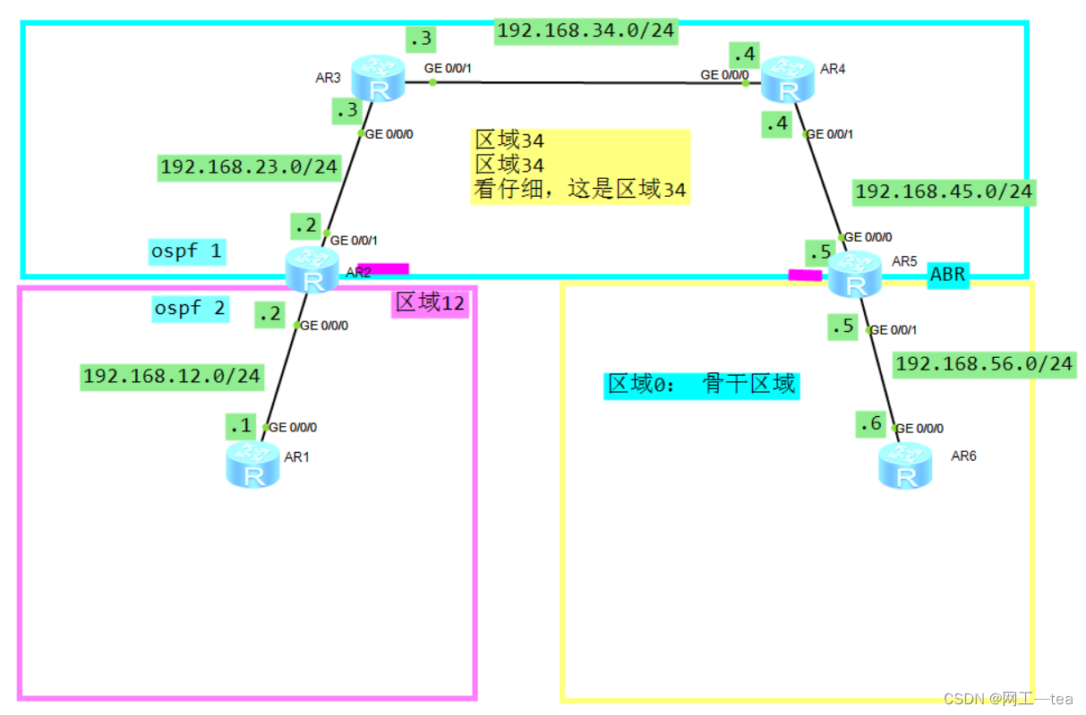
拓扑
需求
1) R1和R6互联互通
配置步骤
1)配置ospf
2) 在R2中配置多进程
3)在R2中配置多进程互相导入
配置命令
备注:如果在上一个实验中,有配置虚链路,记得删除虚链路
[R2]ospf 1
[R2-ospf-1]area 34    //进入区域34
[R2-ospf-1-area-0.0.0.34]undo vlink-peer 5.5.5.5    //删除虚链路


[R5]ospf 1
[R5-ospf-1]area 34
[R5-ospf-1-area-0.0.0.34]undo vlink-peer 2.2.2.2   //删除虚链路

================================================================

 第一步:配置基础配置
 R1的配置:
[R1]ospf 1 router-id 1.1.1.1
[R1-ospf-1]area 12
[R1-ospf-1-area-0.0.0.12]network 192.168.12.0 0.0.0.255

 R2的配置:
[R2]ospf 1 router-id 2.2.2.2
[R2-ospf-1]area 12
[R2-ospf-1-area-0.0.0.12]network 192.168.12.0 0.0.0.255
[R2-ospf-1-area-0.0.0.12]quit
[R2-ospf-1]area 34
[R2-ospf-1-area-0.0.0.34]network 192.168.23.0 0.0.0.255

 R3的配置:
[R3]ospf 1 router-id  3.3.3.3
[R3-ospf-1]area 34
[R3-ospf-1-area-0.0.0.34]network 192.168.23.0 0.0.0.255
[R3-ospf-1-area-0.0.0.34]network 192.168.34.0 0.0.0.255

 R4的配置:
[R4]ospf 1 router-id 4.4.4.4
[R4-ospf-1]area 34
[R4-ospf-1-area-0.0.0.34]network 192.168.34.0 0.0.0.255
[R4-ospf-1-area-0.0.0.34]network 192.168.45.0 0.0.0.255

 R5的配置:
[R5]ospf 1 router-id 5.5.5.5
[R5-ospf-1]area 34
[R5-ospf-1-area-0.0.0.34]network 192.168.45.0 0.0.0.255
[R5-ospf-1-area-0.0.0.34]quit
[R5-ospf-1]area 0
[R5-ospf-1-area-0.0.0.0]network 192.168.56.0 0.0.0.255

 R6的配置:
[R6]ospf 1 router-id 6.6.6.6
[R6-ospf-1]area 0
[R6-ospf-1-area-0.0.0.0]network 192.168.56.0 0.0.0.255


 第二步:在R2中删除ospf 配置
[R2]undo ospf 1

 第三步:在R2中,重新配置ospf
[R2]ospf 1 router-id 2.2.2.2      //配置ospf 进程1
[R2-ospf-1]area 34                //进入区域34
[R2-ospf-1-area-0.0.0.34]network 192.168.23.0 0.0.0.255
[R2-ospf-1-area-0.0.0.34]quit
[R2-ospf-1]quit

[R2]ospf 2 router-id 2.2.2.2    //配置ospf进程2
[R2-ospf-2]area 12              //进入区域12
[R2-ospf-2-area-0.0.0.12]network 192.168.12.0 0.0.0.255

 备注: OSPF进程号,只在本设备生效, 不会在网络中传递
      OSPF进程号的作用: 在一台路由器上,区分不同的OSPF协议
      OSPF不同的进程之间,是相互隔离的,网络是不通的


 第四步:在R2上配置多进程导入
 1)在R2的OSPF进程2中引入外部路由OSPF进程1

[R2]ospf 1
[R2-ospf-1]import-route ospf 2     //把ospf 2 引入到ospf 1 里面去


验证;在OSPF进程1 中引入外部路由协议 OSPF2
     那么在区域34会生产5类的LSA,5类的LSA会全域泛洪
     所以R3/R4/R5/R6都会学习到这条5类的LSA,
     通过这条5类的LSA就可以计算出来去往192.168.12.0/24的外部路由

 2)在R6中验证:查看R6的LSDB数据库:发现有5类的LSA
 <R6>display ospf lsdb

     AS External Database
 Type      LinkState ID    AdvRouter     Age  Len   Sequence   Metric
  External  192.168.12.0    2.2.2.2       423  36    80000002       1

 3)在R6中验证:查看R6的路由表:发现通过5类LSA计算出来了外部路由
 <R6>dis ip routing-table 192.168.12.1

Destination/Mask    Proto   Pre  Cost   NextHop         Interface

 192.168.12.0/24     O_ASE   150  1      192.168.56.5    G0/0/0


验证:既然R6有去往192.168.12.0/24的外部OSPF路由了,那么R6和R1可以互通吗?
     不可以,为什么?
     因为R1没有回程路由?
     那应该怎么办,继续做多进程导入
     在R2中,在OSPF2中,也引入OSPF1

 4)在R2的OSPF进程1中引入外部路由OSPF进程2
[R2]ospf 2
[R2-ospf-2]import-route ospf 1    //把ospf1  引入到ospf 2 里面去


 5)验证:在R1中验证多进程导入结果
 <R1>display ospf lsdb

   OSPF Process 1 with Router ID 1.1.1.1
     Link State Database

             Area: 0.0.0.12
 Type      LinkState ID    AdvRouter          Age  Len   Sequence   Metric
 Router    2.2.2.2         2.2.2.2            456  36    8000000C       1
 Router    1.1.1.1         1.1.1.1            716  36    8000000D       1
 Network   192.168.12.1    1.1.1.1            716  32    80000003       0


      AS External Database
 Type      LinkState ID    AdvRouter          Age  Len   Sequence   Metric
 External  192.168.56.0    2.2.2.2            456  36    80000001       1
 External  192.168.34.0    2.2.2.2            456  36    80000001       1
 External  192.168.23.0    2.2.2.2            456  36    80000001       1
 External  192.168.45.0    2.2.2.2            456  36    80000001       1

备注:有了5类的LSA,就一定会有外部OSPF路由,有了路由,网络就可以互联互通

验证:R1  ping  R6  通
GRE隧道
GRE概念
隧道技术的一种,通用路由封装协议,可用于在不同公司跨互联网传递路由,我们这里使用GRE技术,用于解决OSPF中非骨干区域没有和骨干区域直接相连的场景
GRE原理
本质:
R2通过实现和共同区域34中的ABR-R5路由器建立区域0的邻居关系,从而让R2路由器变为骨干区域路由器,变成ABR, 获取骨干区域的数据库,学习3类的LSA,
从而实现网络互通
原理:
1)GRE(Generic Routing Encapsulation):通用路由封装协议
2)GRE是一种三层隧道封装技术
3)GRE报文结构:
乘客协议:封装前的报文协议称为乘客协议。
封装协议 :GRE Header是由封装协议完成并填充的
传输协议:负责对封装后的报文进行转发的协议称为传输协议。
4)GRE隧道建立:
-GRE隧道是通过隧道两端的Tunnel接口建立的,所以需要在隧道两端的设备上分别配置Tunnel接口。
-GRE的Tunnel接口,需要指定为GRE、 需要指定源IP地址和目的IP地址、需要指定Tunnel接口IP地址。
-源IP地址:隧道的源地址就是实际发送报文的接口IP地址
-目的IP地址:隧道的目的地址就是实际接收报文的接口IP地址
-Tunnel接口IP地址:为了在隧道内建立ospf 邻居关系的,要在区域0宣告
5) GRE使用Tunnel里面的ip地址,作为建立区域0邻居关系的地址,建立一条隧道,通过隧道地址进行互通,真正的建立邻居的隧道地址,在传输过程中不会解封装,通过隧道地址在区域34进行转发,只有到达隧道的终点,才会解封装,漏出真实的地址,实现了跨越多个网络建立了直连的区域0 的邻居关系
GRE 隧道配置-案例1
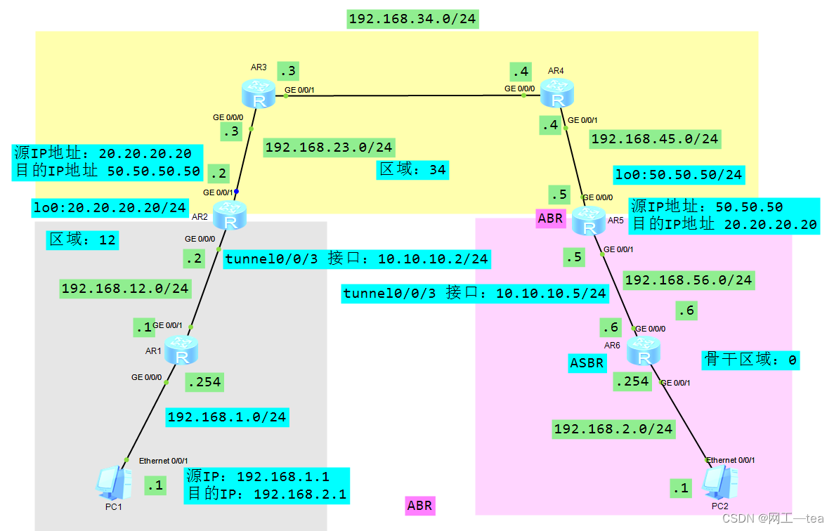
拓扑

需求
需求:实现区域12的R1 和其他区域的路由器互联互通
配置
第一步:配置OSPF基础配置
第二步:建立GRE隧道
1)创建隧道接口
2)给隧道接口配置IP地址
3)配置源IP,使用R2的g0/0/1
4)配置目的IP,使用R5的g0/0/0
第三步:在隧道中,建立ospf 邻居关系
1)把隧道接口的IP地址,宣告进ospf 区域0
第一步:基础配置:OSPF基础配置

 sysname R1
#
interface GigabitEthernet0/0/0
 ip address 192.168.12.1 255.255.255.0
#
ospf 1 router-id 1.1.1.1
 area 0.0.0.12
  network 192.168.12.0 0.0.0.255


 sysname R2
#
interface GigabitEthernet0/0/0
 ip address 192.168.12.2 255.255.255.0
#
interface GigabitEthernet0/0/1
 ip address 192.168.23.2 255.255.255.0
#
ospf 1 router-id 2.2.2.2
 area 0.0.0.34
  network 192.168.23.0 0.0.0.255

 area 0.0.0.12
  network 192.168.12.0 0.0.0.255


 sysname R3
#
interface GigabitEthernet0/0/0
 ip address 192.168.23.3 255.255.255.0
#
interface GigabitEthernet0/0/1
 ip address 192.168.34.3 255.255.255.0
#
ospf 1 router-id 3.3.3.3
 area 0.0.0.34
  network 192.168.23.0 0.0.0.255
  network 192.168.34.0 0.0.0.255

 sysname R4
#
interface GigabitEthernet0/0/0
 ip address 192.168.34.4 255.255.255.0
#
interface GigabitEthernet0/0/1
 ip address 192.168.45.4 255.255.255.0
#
ospf 1 router-id 4.4.4.4
 area 0.0.0.34
  network 192.168.34.0 0.0.0.255
  network 192.168.45.0 0.0.0.255


 sysname R5
#
interface GigabitEthernet0/0/0
 ip address 192.168.45.5 255.255.255.0
#
interface GigabitEthernet0/0/1
 ip address 192.168.56.5 255.255.255.0
#
ospf 1 router-id 5.5.5.5
 area 0.0.0.34
  network 192.168.45.0 0.0.0.255

 area 0.0.0.0
  network 192.168.56.0 0.0.0.255


 sysname R6
#
interface GigabitEthernet0/0/0
 ip address 192.168.56.6 255.255.255.0
#
ospf 1 router-id 6.6.6.6
 area 0.0.0.0
  network 192.168.56.0 0.0.0.255


 第二步:配置gre隧道
 R2配置GRE隧道:
[R2]int tunnel0/0/3    //创建隧道接口
[R2-Tunnel0/0/3]ip address 10.10.10.2 255.255.255.0     //配置隧道接口IP地址(在骨干区域建立ospf邻居)
[R2-Tunnel0/0/3]tunnel-protocol gre      //配置隧道协议GRE
[R2-Tunnel0/0/3]source 192.168.23.2       //配置隧道传输中的源IP (数据报文在隧道传输时候,封装的源IP)
[R2-Tunnel0/0/3]destination 192.168.45.5  //配置隧道传输中的目的IP (数据报文在隧道传输时候,封装的目的IP)

 R5配置gre隧道 :
[R5]int tunnel0/0/3
[R5-Tunnel0/0/3]ip add 10.10.10.5 24
[R5-Tunnel0/0/3]tunnel-protocol gre
[R5-Tunnel0/0/3]source 192.168.45.5
[R5-Tunnel0/0/3]destination 192.168.23.2

 第三步:把隧道的接口IP地址,10.10.10.0/24 宣告到ospf 的骨干区域0
         作用:R2和R5在区域0建立OSPF邻居关系

 R2配置:
[R2]ospf 1
[R2-ospf-1]area 0    //在R2中的创建区域0
[R2-ospf-1-area-0.0.0.0]network 10.10.10.0 0.0.0.255     //宣告隧道接口的IP网段

 R5配置:
[R5]ospf 1
[R5-ospf-1]area 0
[R5-ospf-1-area-0.0.0.0]network 10.10.10.0 0.0.0.255


 第四步:验证与测试
 1)验证R1和R6是否可以通信
R1  ping  R6  可以通

 2) 在R2中验证R2是不是ABR设备
[R2]display ospf brief   //发现R2成为ABR
RouterID: 2.2.2.2            Border Router:  AREA

 3)在R2中验证R2中有没有 骨干区域的LSDB数据库
[R2]display ospf lsdb  //发现R2中有区域0的数据库

 4)在R2中验证接口的隧道信息,看隧道接口是否UP
[R2]display interface Tunnel   //查看接口隧道接口信息,接口状态和协议状态都要是up
 Tunnel0/0/3 current state :  UP
 Line protocol current state :  UP

 5)在R2中查看隧道接口的IP地址和状态
[R2]display ip interface brief
Interface               IP Address/Mask     Physical   Protocol
Tunnel0/0/3             10.10.10.2            up         up

 6)在R2中查看隧道信息
[R2]display tunnel-info all    //查看隧道信息

 7)在R2中查看路由
[R2] display ip routing-table 192.168.56.6  //查看去往56.0网段的下一跳和出接口
GRE 隧道配置-案例2
拓扑
需求
需求:实现区域12的R1 和其他区域的路由器互联互通
配置
第一步:配置OSPF基础配置
第二步:建立GRE隧道
1)创建隧道接口
2)给隧道接口配置IP地址
3)配置源IP,使用loopback 接口
4)配置目的IP,使用loopback 接口
第三步:在隧道中,建立ospf 邻居关系
1)把隧道接口的IP地址,宣告进ospf 区域0
2)把隧道的源IP地址宣告进ospf 区域34
-R2在区域34 宣告 20.20.20.0 0.0.0.255
-R5 在区域34 宣告 50.50.50.0 0.0.0.255
第一步:基础配置:OSPF基础配置

 sysname R1
#
interface GigabitEthernet0/0/0
 ip address 192.168.1.254 255.255.255.0
#
interface GigabitEthernet0/0/1
 ip address 192.168.12.1 255.255.255.0
#
ospf 1 router-id 1.1.1.1
 area 0.0.0.12
  network 192.168.1.0 0.0.0.255
  network 192.168.12.0 0.0.0.255


 sysname R2
#
interface GigabitEthernet0/0/0
 ip address 192.168.12.2 255.255.255.0
#
interface GigabitEthernet0/0/1
 ip address 192.168.23.2 255.255.255.0
#
ospf 1 router-id 2.2.2.2
 area 0.0.0.34
  network 192.168.23.0 0.0.0.255

 area 0.0.0.12
  network 192.168.12.0 0.0.0.255


 sysname R3
#
interface GigabitEthernet0/0/0
 ip address 192.168.23.3 255.255.255.0
#
interface GigabitEthernet0/0/1
 ip address 192.168.34.3 255.255.255.0
#
ospf 1 router-id 3.3.3.3
 area 0.0.0.34
  network 192.168.23.0 0.0.0.255
  network 192.168.34.0 0.0.0.255

 sysname R4
#
interface GigabitEthernet0/0/0
 ip address 192.168.34.4 255.255.255.0
#
interface GigabitEthernet0/0/1
 ip address 192.168.45.4 255.255.255.0
#
ospf 1 router-id 4.4.4.4
 area 0.0.0.34
  network 192.168.34.0 0.0.0.255
  network 192.168.45.0 0.0.0.255


 sysname R5
#
interface GigabitEthernet0/0/0
 ip address 192.168.45.5 255.255.255.0
#
interface GigabitEthernet0/0/1
 ip address 192.168.56.5 255.255.255.0
#
ospf 1 router-id 5.5.5.5
 area 0.0.0.34
  network 192.168.45.0 0.0.0.255

 area 0.0.0.0
  network 192.168.56.0 0.0.0.255

 sysname R6
#
interface GigabitEthernet0/0/0
 ip address 192.168.56.6 255.255.255.0
#
ospf 1 router-id 6.6.6.6
 area 0.0.0.0
  network 192.168.56.0 0.0.0.255


 第二步:配置GRE隧道
 sysname R2
#
interface LoopBack0
 ip address 20.20.20.20 255.255.255.0   //配置loopback接口,
 做隧道中的源IP地址 ,为什么,因为稳定,不会down


interface Tunnel0/0/3     //创建隧道接口
 ip address 10.10.10.2 255.255.255.0   //给隧道接口配置IP地址,(在已经建立的隧道, 在ospf中区域0建立邻居)
 tunnel-protocol gre     //把隧道的模式,定义为GRE
 source 20.20.20.20       //进入隧道的数据要进行二次封装,在原始的数据包的IP头部前,在加1层IP头部,封装新的源IP和目的IP
 destination 50.50.50.50  //二次封装的目的IP地址


 sysname R5
#
interface LoopBack0
 ip address 50.50.50.50 255.255.255.0
#
interface Tunnel0/0/3
 ip address 10.10.10.5 255.255.255.0
 tunnel-protocol gre
 source 50.50.50.50
 destination 20.20.20.20


  第三步:在隧道中,建立ospf 邻居关系
   sysname R2
#
 ospf 1 router-id 2.2.2.2
 area 0.0.0.0                    //创建区域0
    network 10.10.10.0 0.0.0.255    //把隧道接口的IP地址,宣告进区域0,让R2变成ABR
 area 0.0.0.12
  network 192.168.12.0 0.0.0.255
 area 0.0.0.34
   network 20.20.20.0 0.0.0.255     //把loopback接口的IP地址,宣告进区域34
  network 192.168.23.0 0.0.0.255


  sysname R5
#
ospf 1 router-id 5.5.5.5
 area 0.0.0.0
    network 10.10.10.0 0.0.0.255
  network 192.168.56.0 0.0.0.255
 area 0.0.0.34
   network 50.50.50.0 0.0.0.255
  network 192.168.45.0 0.0.0.255


 第四步:验证与测试
 1)验证R1和R6是否可以通信
R1  ping  R6  可以通

 2) 在R2中验证R2是不是ABR设备
[R2]display ospf brief   //发现R2成为ABR
RouterID: 2.2.2.2          Border Router:  AREA

 3)在R2中验证R2中有没有 骨干区域的LSDB数据库
[R2]display ospf lsdb  //发现R2中有区域0的数据库

 4)在R2中验证接口的隧道信息,看隧道接口是否UP
[R2]display interface Tunnel   //查看接口隧道接口信息,接口状态和协议状态都要是up
 Tunnel0/0/3 current state : UP
 Line protocol current state : UP

 5)在R2中查看隧道接口的IP地址和状态
[R2]display ip interface brief
Interface               IP Address/Mask     Physical   Protocol
Tunnel0/0/3             10.10.10.2          up         up

 6)在R2中查看隧道信息
[R2]display tunnel-info all    //查看隧道信息

[R2] display ip routing-table 192.168.2.1   //查看去往2.0网段的下一跳和出接口
OSPF开销选路
概念
OSPF以开销做为度量值,每一个激活了OSPF的接口都会维护一个开销值,默认情况下,路由器的千兆接口开销值为1,代表从一个路由器的网段到另一个路由器网段的距离
原理
cost 值是以数据发送的出方向 (也就是路由传递的入方向)之和作为累计开销值,开销值越小越优,如果OSPF路由器从多个邻居收到一条相同的路由,OSPF邻居会优先选择开销值小的路由,从而将这条路由计算加载到路由表中,影响转发路径
配置
需求
1) 为增加OSPF骨干区域的可靠性,增加AR8设备作为备份设备,与区域0的路由器建立邻居关系
2) 建立邻居关系后,发现转发路径改为AR1-AR2-AR8-AR5-AR6,由于AR8作为备份设备,性能不要,链路带宽不高,无法承载较大的数据转发流量
3)通过开销值选路,优先选择AR1-AR2-AR3-AR4-AR5-AR6为最优转发路径
拓扑

配置思路
1) 配置互联路由器接口,配置PC1、PC2的 IP 地址
2)配置OSPF多区域
3)增加AR8和其他骨干区域路由器建立区域0的邻居关系
4)修改R2的g0/0/2和R3的g0/0/2开销值
5)测试数据转发路径
6)R8设备增加板块

配置命令
第一步:配置PC的接口IP地址

第二步:配置OSPF

  sysname R1
#
interface GigabitEthernet0/0/0
 ip address 192.168.1.254 255.255.255.0
#
interface GigabitEthernet0/0/1
 ip address 192.168.12.1 255.255.255.0
 ospf cost 1
#
ospf 1 router-id 1.1.1.1
 area 0.0.0.12
  network 192.168.1.0 0.0.0.255
  network 192.168.12.0 0.0.0.255


  sysname R2
#
interface GigabitEthernet0/0/0
 ip address 192.168.12.2 255.255.255.0
 ospf cost 1
#
interface GigabitEthernet0/0/1
 ip address 192.168.23.2 255.255.255.0
#
interface GigabitEthernet0/0/2
 ip address 192.168.28.2 255.255.255.0
#
ospf 1 router-id 2.2.2.2
 area 0.0.0.0
  network 192.168.23.0 0.0.0.255
  network 192.168.28.0 0.0.0.255
 area 0.0.0.12
  network 192.168.12.0 0.0.0.255

  sysname R3
#
interface GigabitEthernet0/0/0
 ip address 192.168.23.3 255.255.255.0
#
interface GigabitEthernet0/0/1
 ip address 192.168.34.3 255.255.255.0
#
interface GigabitEthernet0/0/2
 ip address 192.168.38.3 255.255.255.0
#
ospf 1 router-id 3.3.3.3
 area 0.0.0.0
  network 192.168.23.0 0.0.0.255
  network 192.168.34.0 0.0.0.255
  network 192.168.38.0 0.0.0.255

  sysname R4
#
interface GigabitEthernet0/0/0
 ip address 192.168.34.4 255.255.255.0
#
interface GigabitEthernet0/0/1
 ip address 192.168.45.4 255.255.255.0
#
interface GigabitEthernet0/0/2
 ip address 192.168.48.4 255.255.255.0

#
ospf 1 router-id 4.4.4.4
 area 0.0.0.0
  network 192.168.34.0 0.0.0.255
  network 192.168.45.0 0.0.0.255
  network 192.168.48.0 0.0.0.255

   sysname R5
#
interface GigabitEthernet0/0/0
 ip address 192.168.45.5 255.255.255.0
#
interface GigabitEthernet0/0/1
 ip address 192.168.56.5 255.255.255.0
#
interface GigabitEthernet0/0/2
 ip address 192.168.58.5 255.255.255.0
#
ospf 1 router-id 5.5.5.5
 area 0.0.0.0
  network 192.168.45.0 0.0.0.255
  network 192.168.58.0 0.0.0.255
 area 0.0.0.56
  network 192.168.56.0 0.0.0.255


  sysname R6
#
interface GigabitEthernet0/0/0
 ip address 192.168.56.6 255.255.255.0
#
interface GigabitEthernet0/0/1
 ip address 192.168.2.254 255.255.255.0
#
ospf 1 router-id 6.6.6.6
 area 0.0.0.56
  network 192.168.2.0 0.0.0.255
  network 192.168.56.0 0.0.0.255


 sysname R8
#
interface GigabitEthernet0/0/0
 ip address 192.168.38.8 255.255.255.0
#
interface GigabitEthernet0/0/1
 ip address 192.168.28.8 255.255.255.0
#
interface GigabitEthernet0/0/2
 ip address 192.168.48.8 255.255.255.0
#
interface GigabitEthernet6/0/3
 ip address 192.168.58.8 255.255.255.0
#
ospf 1 router-id 8.8.8.8
 area 0.0.0.0
  network 192.168.28.0 0.0.0.255
  network 192.168.38.0 0.0.0.255
  network 192.168.48.0 0.0.0.255
  network 192.168.58.0 0.0.0.255

   第三步:修改R2的g0/0/2和R3的g0/0/2开销值
  R2的配置:
 interface GigabitEthernet0/0/2
    ip address 192.168.28.2 255.255.255.0
     ospf cost 5

  R3的配置:
 interface GigabitEthernet0/0/2
    ip address 192.168.38.3 255.255.255.0
      ospf cost 5

 R5的配置:
 interface GigabitEthernet0/0/2
    ip address 192.168.58.5 255.255.255.0
    ospf cost 5

 R4的配置:
 interface GigabitEthernet0/0/2
    ip address 192.168.48.4 255.255.255.0
    ospf cost 5

 第四步:验证与测试
 PC1  ping  PC2 通
 PC2  ping  PC1 通

 在PC1中做tracert  192.168.2.1
 在PC2中做tracert  192.168.1.1

  PC>tracert 192.168.2.1
traceroute to 192.168.2.1, 8 hops max
(ICMP), press Ctrl+C to stop
 1  192.168.1.254   <1 ms  16 ms  16 ms
 2  192.168.12.2   15 ms  16 ms  16 ms
 3  192.168.23.3   15 ms  31 ms  16 ms
 4  192.168.34.4   16 ms  31 ms  31 ms
 5  192.168.45.5   16 ms  31 ms  31 ms
 6  192.168.56.6   16 ms  31 ms  31 ms
 7  192.168.2.1    32 ms  47 ms  31 ms


在R1中查看路由表:
<R1>display ip routing-table protocol ospf
Destination/Mask    Proto   Pre   Cost     NextHop        Interface

 192.168.23.0/24     OSPF    10     2       192.168.12.2    G0/0/1
 192.168.28.0/24     OSPF    10     6       192.168.12.2    G0/0/1


 在R2中查看接口开销值:
<R2>display ospf interface  g0/0/1
 Interface: 192.168.23.2 (GigabitEthernet0/0/1)
   Cost: 1         State: DR        Type: Broadcast    MTU: 1500
 Priority: 1
 Designated Router: 192.168.23.2
 Backup Designated Router: 192.168.23.3
 Timers: Hello 10 , Dead 40 , Poll  120 , Retransmit 5 , Transmit Delay 1

 <R2>display ospf interface  g0/0/2
 Interface: 192.168.28.2 (GigabitEthernet0/0/2)
   Cost: 5        State: BDR       Type: Broadcast    MTU: 1500
 Priority: 1
 Designated Router: 192.168.28.8
 Backup Designated Router: 192.168.28.2
 Timers: Hello 10 , Dead 40 , Poll  120 , Retransmit 5 , Transmit Delay 1


在R3中查看接口开销值:
<R3>display ospf interface  g0/0/1
 Interface: 192.168.34.3 (GigabitEthernet0/0/1)
   Cost: 1        State: DR        Type: Broadcast    MTU: 1500
 Priority: 1
 Designated Router: 192.168.34.3
 Backup Designated Router: 192.168.34.4
 Timers: Hello 10 , Dead 40 , Poll  120 , Retransmit 5 , Transmit Delay 1


 <R3>display ospf interface  g0/0/2
 Interface: 192.168.38.3 (GigabitEthernet0/0/2)
   Cost: 5         State: BDR       Type: Broadcast    MTU: 1500
 Priority: 1
 Designated Router: 192.168.38.8
 Backup Designated Router: 192.168.38.3
 Timers: Hello 10 , Dead 40 , Poll  120 , Retransmit 5 , Transmit Delay 1
路由过滤
场景:
超市有促销,鸡蛋免费送,突然涌入了很多人,年轻人都冲进来了,接待不过来,现在我只让60岁以上的老人先进来,其他人不允许进来,所以要在门口贴一个策略,就好比引入外部静态路由,引入到OSPF内部的路由数量太多了,导致内网不安全并且路由表规模过大,因此要在引入路由时加上路由策略进行控制
原理
我们要对引入的路由外部路由进行控制,就要在引入外部路由时调用策略,具体要让哪条路由引入,我们首先要考虑如何抓取路由,这时我们想到了acl,因为import-route下面无法直接调用acl,所以我们要学习一个路由策略工具route-policy,该工具可以在import-route下直接调用
1)Route-policy解析:
route-policy 2.0 permit/deny node 10
route-policy的名字:2.0
动作:permit/deny 允许/拒接 (和acl相似)
node:节点编号10 (写10,为什么不写1,增加条目时候不方便)
2)Route-policy使用方法:
要和acl关联起来,if-match acl 2000
允许acl抓取的路由进来,只要acl匹配的路由,route-policy就允许你进来,route-policy像一个中介
配置
需求
1)企业内网部分网络运行OSPF协议,但是服务器所在部门使用静态
2)配置路由控制策略,确保PC1仅仅能访问Server2
拓扑

配置步骤
1) 配置PC1,Server1、Server2的IP地址
2) 配置OSPF区域123、配置OSPF区域0
3)配置OSPF域内与外部服务器互通
4)将外部路由引入到OSPF内部
5)配置路由策略PC1只允许访问Server2
配置命令
1.配置终端PC、服务器的IP地址
 2.配置OSPF多区域

AR2配置:
ospf 1 router-id 2.2.2.2
 area 0.0.0.123
  network 192.168.23.0 0.0.0.255

AR3配置:
ospf 1 router-id 3.3.3.3
 area 0.0.0.123
  network 192.168.23.0 0.0.0.255
  network 192.168.34.0 0.0.0.255

AR4配置:
 ospf 1 router-id 4.4.4.4
 area 0.0.0.0
  network 192.168.45.0 0.0.0.255
 area 0.0.0.123
  network 192.168.34.0 0.0.0.255

 AR5配置:
 ospf 1 router-id 5.5.5.5
 area 0.0.0.0
  network 192.168.3.0 0.0.0.255
  network 192.168.45.0 0.0.0.255

 3.配置与外部路由互通
AR2配置:
ip route-static 192.168.1.0 255.255.255.0 192.168.12.1
ip route-static 192.168.2.0 255.255.255.0 192.168.12.1

AR1配置:
ip route-static 192.168.3.0 255.255.255.0 192.168.12.2

 4.AR2上引入外部路由
 AR2的配置:

ospf 1 router-id 2.2.2.2
 import-route static
 area 0.0.0.123
  network 192.168.23.0 0.0.0.255

 5.配置策略,只引入2.0路由
 AR2的配置:

acl number 2000        //匹配路由
 rule 5 permit source 192.168.2.0 0.0.0.255
#
route-policy 2.0 permit node 10     //动作: 允许acl中匹配的路由
 if-match acl 2000
#
ospf 1 router-id 2.2.2.2
 import-route static route-policy 2.0            //调用策略
 area 0.0.0.123
  network 192.168.23.0 0.0.0.255

 6、验证结果:
区域123的R3-R4  无法访问server1  --没有5类的LSA,没有路由
区域0的R5和PC1  无法访问server1  --没有5类的LSA,没有路由

经过验证,我们发现PC只能访问server2  无法访问sever1 了
但是区域123的路由器也无法访问server1 了

能否实现 区域123的设备能够访问server 1  不让区域0的用户主机访问server 1


--------------------------------------------

 扩展小实验:
 1)在ASBR-R2上删除调用的路由策略
[R2-ospf-1]undo import-route  static       :删除调用的路由策略

 2) 在ASBR-R2上重新引入静态路由,不调用路由策略
[R2]ospf 1
[R2-ospf-1]import-route static          :重新引入静态路由到ospf ,不调用路由策略


 3) 在R5 中创建acl 2000 过滤192.168.2.0  允许2.0-23.0 --34.0
[R5]acl 2000
[R5-acl-basic-2000]rule 10 permit source 192.168.2.0 0.0.0.255
[R5-acl-basic-2000]rule 20 permit source 192.168.23.0 0.0.0.255
[R5-acl-basic-2000]rule 30 permit source 192.168.34.0 0.0.0.255
[R5-acl-basic-2000]quit

 4)在R5中创建路由策略  匹配acl 2000   只允许外部2.0通过,和内部的23.0  34.0
[R5]route-policy 2.0 permit node 10
[R5-route-policy]if-match acl 2000
[R5-route-policy]quit

 5)在R5的ospf  1 进程1 下  ,使用 filter-policy 代用路由策略(在入方向调用)
[R5]ospf 1
[R5-ospf-1]filter-policy route-policy  2.0 import

 验证:数据库中5类的LSA  192.168.1.0 依然存在

 <R5>display  ospf lsdb
   OSPF Process 1 with Router ID 5.5.5.5
             Area: 0.0.0.0
 Type      LinkState ID    AdvRouter          Age  Len   Sequence   Metric
 Router    4.4.4.4         4.4.4.4            110  36    80000009       1
 Router    5.5.5.5         5.5.5.5             82  48    80000009       1
 Network   192.168.45.4    4.4.4.4            110  32    80000006       0
 Sum-Net   192.168.23.0    4.4.4.4            176  28    80000005       2
 Sum-Net   192.168.34.0    4.4.4.4            176  28    80000005       1
 Sum-Asbr  2.2.2.2         4.4.4.4           1638  28    80000001       2


     AS External Database
 Type      LinkState ID    AdvRouter          Age  Len   Sequence   Metric
 External  192.168.2.0     2.2.2.2           1640  36    80000001       1
  External  192.168.1.0     2.2.2.2           1640  36    80000001       1


 验证:发现IP核心路由表中没有去往192.168.1.0的路由
 [R5]dis ip routing-table protocol ospf
Route Flags: R - relay, D - download to fib
------------------------------------------------------------------------------
Public routing table : OSPF
         Destinations : 3        Routes : 3

OSPF routing table status : <Active>
         Destinations : 3        Routes : 3

Destination/Mask    Proto     Pre   Cost      NextHop         Interface

 192.168.2.0/24     O_ASE     150     1       192.168.45.4    G0/0/0
 192.168.23.0/24    OSPF      10      3       192.168.45.4    G0/0/0
 192.168.34.0/24    OSPF      10      2       192.168.45.4    G0/0/0


备注:
在区域中,使用filter 调用 acl  过滤的是 3类的LSA

在OSPF进程下,不进入区域,只是在进程下,使用filter-policy  调用路由策略
过滤是路由,不是LSA
LSA过滤
概念
在进行OSPF路由管理时,不但可以对路由进行过滤,也可以对LSA进行过滤,3类LSA本质上还是路由过滤,所以我们可以通过过滤LSA实现对路由的过滤,因为是3类LSA通过计算生成的路由。
原理
使用acl匹配LSA信息,使用专门fliter 调用acl 实现对LSA的过滤
分析:本实验中,可以在区域0的出方向调用该策略,也可以在区域56的入方向调用该策略,如果在区域0 的出方向调用策略的话,会影响到其他区域,导致其他区域也无法学习到这条LSA。因此要在区域56的入方向调用这个acl,并且只允许拒绝12.0的这条3类LSA,允许其他的3类LSA进入到该区域56中
配置
需求
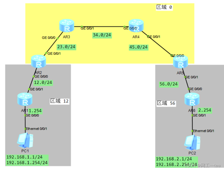
区域56内的用户,不能访问区域12的路由
拓扑
配置步骤
1) 配置PC1ip地址,配置OSPF接口地址
2) 配置OSPF多区域
3) 配置LSA策略过滤策略
配置命令
1.配置PCip地址
2.配置路由器接口IP地址
3.配置OSPF多区域

AR1配置:
ospf 1 router-id 1.1.1.1
  area 0.0.0.12
    network 192.168.1.0 0.0.0.255
    network 192.168.12.0 0.0.0.255

AR2配置:
ospf 1 router-id 2.2.2.2
  area 0.0.0.0
    network 192.168.23.0 0.0.0.255
  area 0.0.0.12
    network 192.168.12.0 0.0.0.255

AR3配置:
ospf 1 router-id 3.3.3.3
  area 0.0.0.0
    network 192.168.23.0 0.0.0.255
    network 192.168.34.0 0.0.0.255

AR4配置:
ospf 1 router-id 4.4.4.4
  area 0.0.0.0
    network 192.168.34.0 0.0.0.255
    network 192.168.45.0 0.0.0.255

AR5配置:
ospf 1 router-id 5.5.5.5
  area 0.0.0.0
    network 192.168.45.0 0.0.0.255
  area 0.0.0.56
    network 192.168.56.0 0.0.0.255
AR6配置
ospf 1 router-id 6.6.6.6
 area 0.0.0.56
  network 192.168.2.0 0.0.0.255
  network 192.168.56.0 0.0.0.255

 4.配置LSA过滤
 R5上配置:区域56的ABR上配置

acl number 2000
 rule 5 deny source 192.168.12.0 0.0.0.255
 rule 10 permit
 #
ospf 1 router-id 5.5.5.5
 area 0.0.0.0
  network 192.168.45.0 0.0.0.255
 area 0.0.0.56
  filter 2000 import
  network 192.168.56.0 0.0.0.255