目录
1.简介
MPS
该参数含义是一个TLP包里携带的有效净荷的最大值是多少字节(该限制条件同时适用于写操作和读操作)。
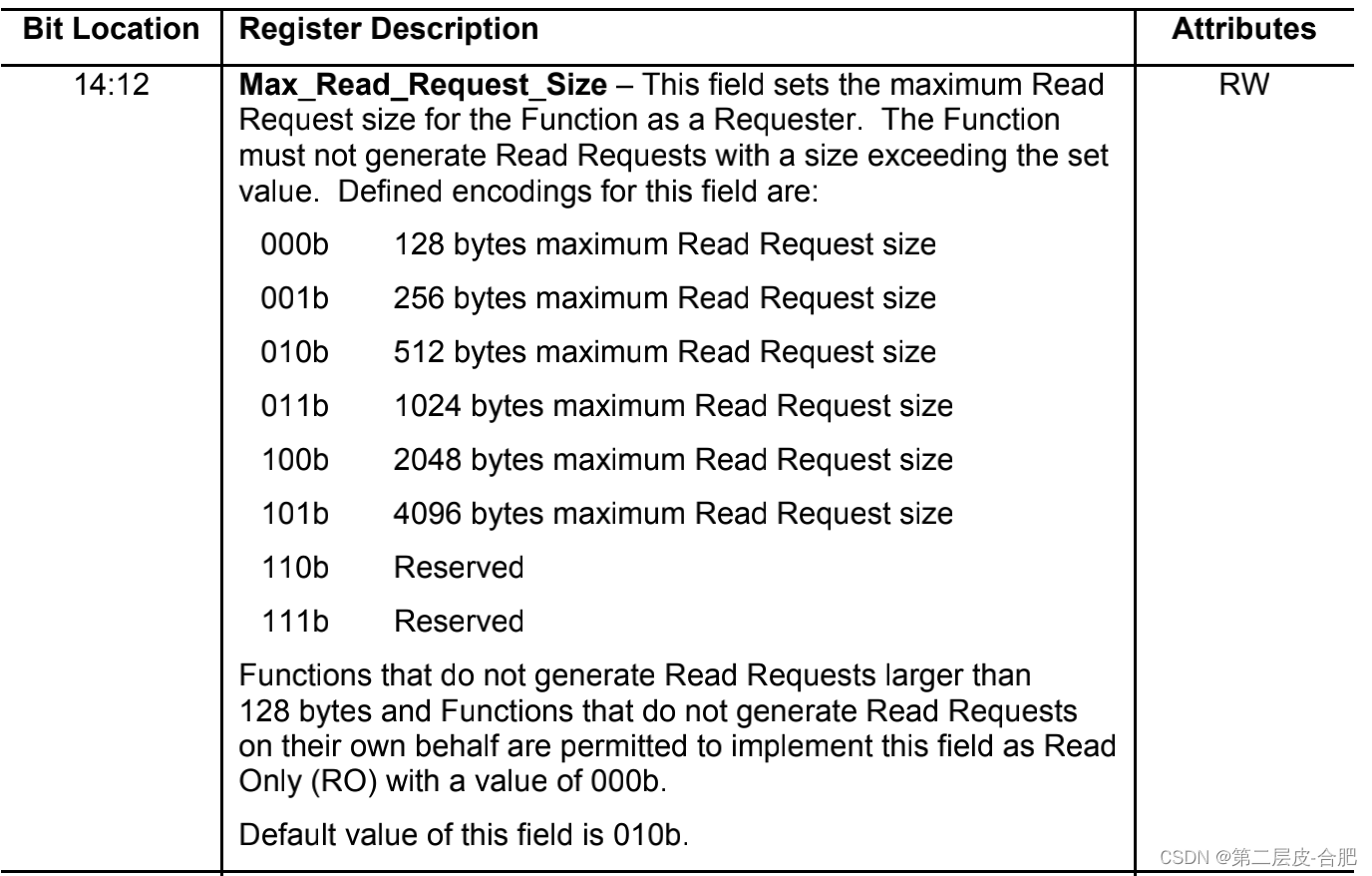
MRRS
该参数含义是一个TLP读请求包,一次最多能向接收端请求读出多少字节。(MRRS参数出现的原因大家有没有想过……其实设定MRRS的原因是为了避免某个设备长时间占用总线)

2.主要功能作用
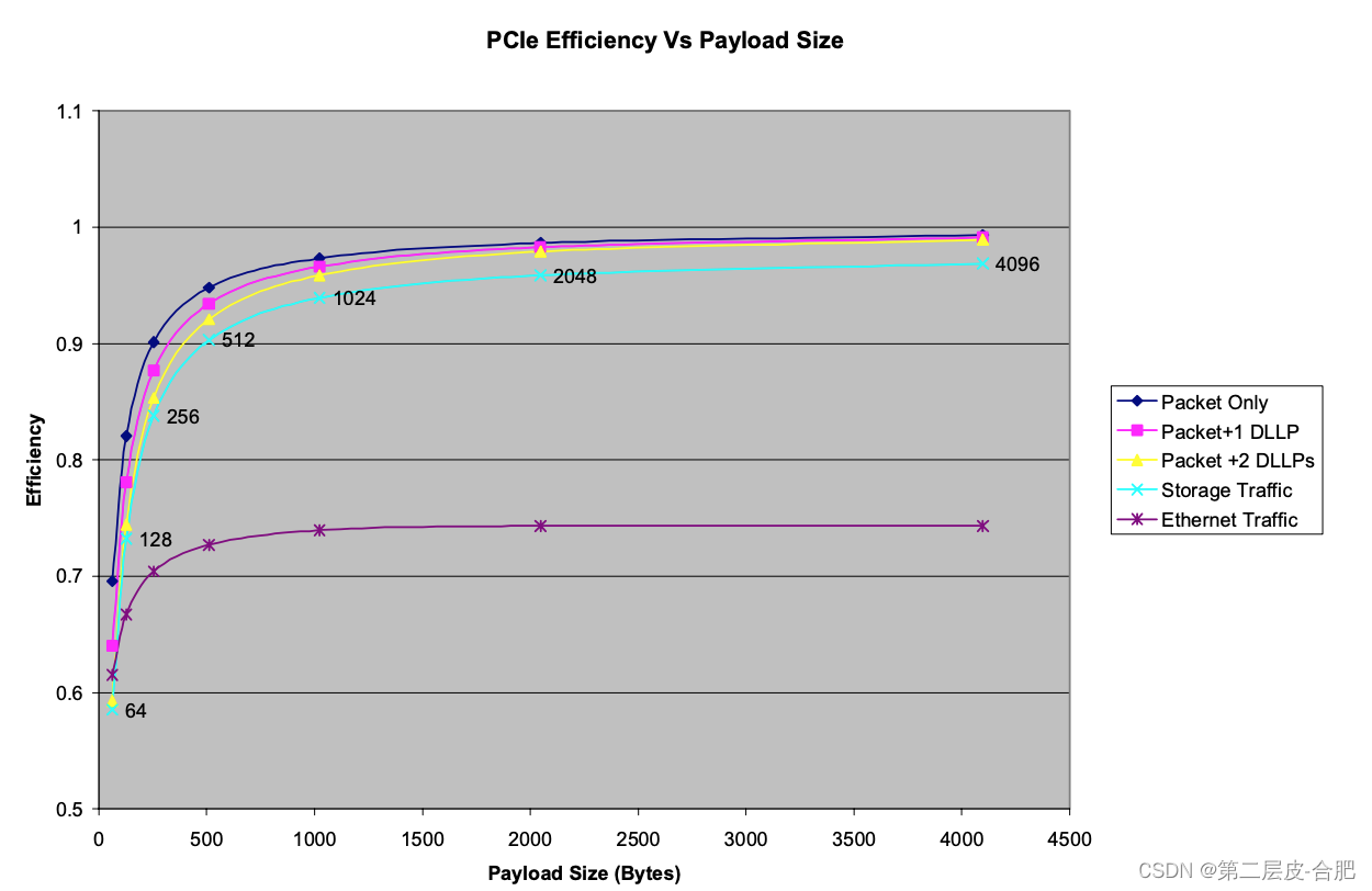
在MPS在PCIe整体性能中,有至关重要的作用。随着MPS大小的增加,PCIe传输效率也在不断的提升。不过,在x86的机器中,RC端的MPS通常是128B/256B。在ARM CPU中,为了追求高效性能,部分场景也会设置为512B。
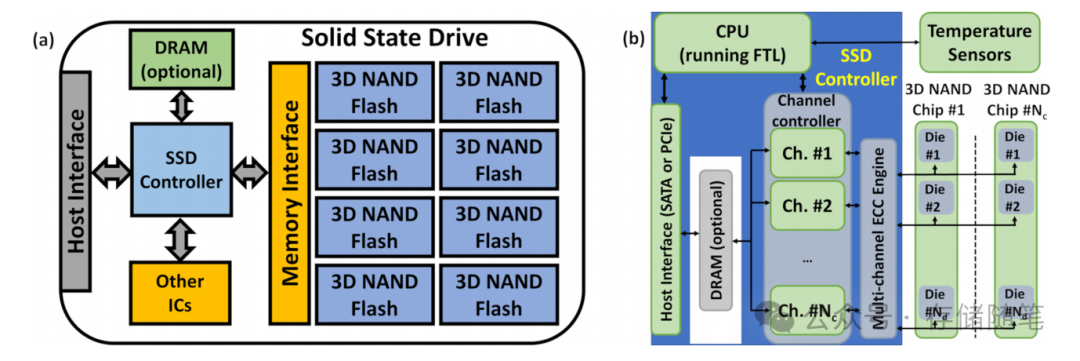
整个PCIe系统中,MPS的大小,跟RC、PCIe Switch、Endpoint都有相互的影响,最终TLP传输的数据大小取决与MPS最小的一个设备。比如下图示例,RC MPS=256B,PCIe Switch MPS=512B,但是EP3 MPS=128B。所以最终数据传输的大小采用的是MPS=128B。
以下是一个实例
lspci -s 01:00.0 -vvvv
01:00.0 Non-Volatile memory controller: Toshiba Corporation Device 0116 (prog-if 02 [NVM Express])
	Subsystem: Toshiba Corporation Device 0001
	Control: I/O- Mem+ BusMaster+ SpecCycle- MemWINV- VGASnoop- ParErr- Stepping- SERR- FastB2B- DisINTx+
	Status: Cap+ 66MHz- UDF- FastB2B- ParErr- DEVSEL=fast >TAbort- <TAbort- <MAbort- >SERR- <PERR- INTx-
	Latency: 0, Cache Line Size: 64 bytes
	Interrupt: pin A routed to IRQ 16
	NUMA node: 0
	Region 0: Memory at 96200000 (64-bit, non-prefetchable) [size=16K]
	Capabilities: [40] Express (v2) Endpoint, MSI 00
		DevCap:	MaxPayload 256 bytes, PhantFunc 0, Latency L0s unlimited, L1 unlimited
			ExtTag- AttnBtn- AttnInd- PwrInd- RBE+ FLReset+ SlotPowerLimit 25.000W
		DevCtl:	Report errors: Correctable+ Non-Fatal+ Fatal+ Unsupported+
			RlxdOrd- ExtTag- PhantFunc- AuxPwr- NoSnoop- FLReset-
			MaxPayload 256 bytes, MaxReadReq 512 bytes
		DevSta:	CorrErr- UncorrErr- FatalErr- UnsuppReq- AuxPwr- TransPend-
		LnkCap:	Port #0, Speed 8GT/s, Width x4, ASPM L1, Exit Latency L0s <2us, L1 <32us
			ClockPM- Surprise- LLActRep- BwNot- ASPMOptComp+
		LnkCtl:	ASPM L1 Enabled; RCB 64 bytes Disabled- CommClk+
			ExtSynch- ClockPM- AutWidDis- BWInt- AutBWInt-
		LnkSta:	Speed 8GT/s, Width x4, TrErr- Train- SlotClk+ DLActive- BWMgmt- ABWMgmt-
		DevCap2: Completion Timeout: Range AB, TimeoutDis+, LTR+, OBFF Not Supported
		DevCtl2: Completion Timeout: 50us to 50ms, TimeoutDis-, LTR+, OBFF Disabled
		LnkCtl2: Target Link Speed: 8GT/s, EnterCompliance- SpeedDis-
			 Transmit Margin: Normal Operating Range, EnterModifiedCompliance- ComplianceSOS-
			 Compliance De-emphasis: -6dB
		LnkSta2: Current De-emphasis Level: -6dB, EqualizationComplete+, EqualizationPhase1+
			 EqualizationPhase2+, EqualizationPhase3+, LinkEqualizationRequest-
	Capabilities: [80] Power Management version 3
		Flags: PMEClk- DSI- D1- D2- AuxCurrent=0mA PME(D0-,D1-,D2-,D3hot-,D3cold-)
		Status: D0 NoSoftRst+ PME-Enable- DSel=0 DScale=0 PME-
	Capabilities: [90] MSI: Enable- Count=1/32 Maskable+ 64bit+
		Address: 0000000000000000  Data: 0000
		Masking: 00000000  Pending: 00000000
	Capabilities: [b0] MSI-X: Enable+ Count=32 Masked-
		Vector table: BAR=0 offset=00002000
		PBA: BAR=0 offset=00003000
3.MPS控制策略
pcie_bus_tune_off   Disable PCIe MPS (Max Payload Size)
                tuning and use the BIOS-configured MPS defaults.
        pcie_bus_safe   Set every device's MPS to the largest value
                supported by all devices below the root complex.
        pcie_bus_perf   Set device MPS to the largest allowable MPS
                based on its parent bus. Also set MRRS (Max
                Read Request Size) to the largest supported
                value (no larger than the MPS that the device
                or bus can support) for best performance.
        pcie_bus_peer2peer  Set every device's MPS to 128B, which
                every device is guaranteed to support. This
                configuration allows peer-to-peer DMA between
                any pair of devices, possibly at the cost of
                reduced performance.  This also guarantees
                that hot-added devices will work.
4.如何更改
Linux系统中通过lspci和setpci可以查询和修改MPS/MRRS参数。
比如:lspci查看设备DevCap寄存器中MPS=512B,最终传输用的MPS=256B,MRRS=4KB。
lspci -s 04:00.0 -vvv | grep DevCtl: -C 2
DevCap: MaxPayload 512 bytes, PhantFunc 0, Latency L0s unlimited, L1 unlimited
ExtTag+ AttnBtn- AttnInd- PwrInd- RBE+ FLReset+
DevCtl: Report errors: Correctable- Non-Fatal+ Fatal+ Unsupported-
RlxdOrd+ ExtTag+ PhantFunc- AuxPwr- NoSnoop+ FLReset-
MaxPayload 256 bytes, MaxReadReq 4096 bytes
如果需要修改MPS或者MRRS,需要先找到Device Control Register中MPS和MRRS的位置,如PCIe Spec定义,MPS在bit5-7,MRRS在bit12-14. 同时Device Control Register的offset是0x8h。